Sensor head for use with implantable devices

a technology of implantable devices and sensor heads, applied in the field of sensor heads utilized with implantable devices, can solve the problems of counter electrode limitations, depressed function, and inability to accurately measure glucose concentration of sensors, and achieve the effects of facilitating oxygen transport across the membrane, enhancing enzyme reaction function, and facilitating oxygen transpor

Inactive Publication Date: 2008-12-30
DEXCOM INC
View PDF396 Cites 868 Cited by
  • Summary
  • Abstract
  • Description
  • Claims
  • Application Information

AI Technical Summary

Benefits of technology

[0015]The sensor heads of the present invention include a multi-region membrane that controls the number of species that are able to reach the surface of the electrodes. In particular, such a membrane allows the passage of desired substrate molecules (e.g. oxygen and glucose) and rejects other larger molecules that may interfere with accurate detection of an analyte. The sensor heads of the present invention also provide a larger counter electrode reactive surface that balances the current between the working and counter electrodes, thereby minimizing negative potential extremes that may interfere with accurate analyte detection.
[0018]The sensor head, membrane architectures, devices and methods of the present invention allow for the collection of continuous information regarding desired analyte levels (e.g. glucose). Such continuous information enables the determination of trends in glucose levels, which can be extremely important in the management of diabetic patients.Definitions
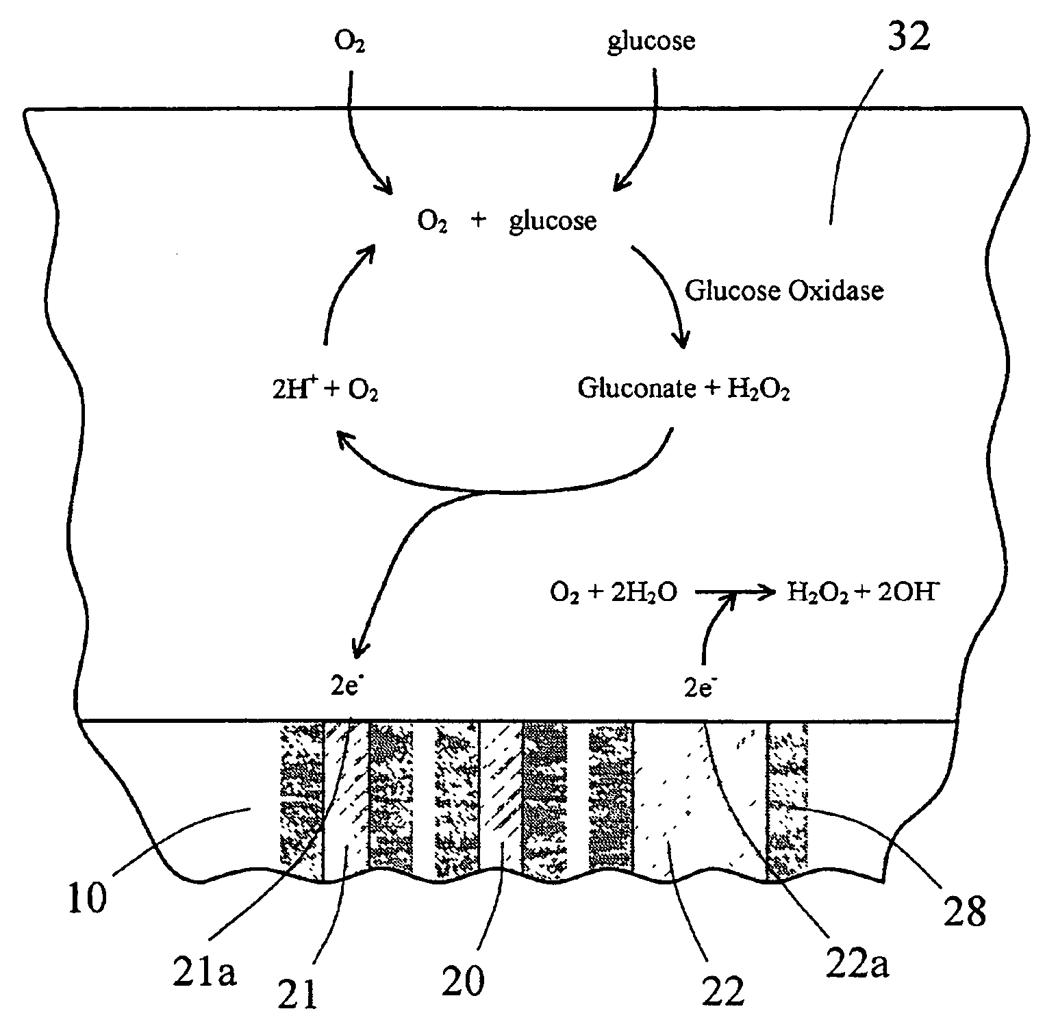
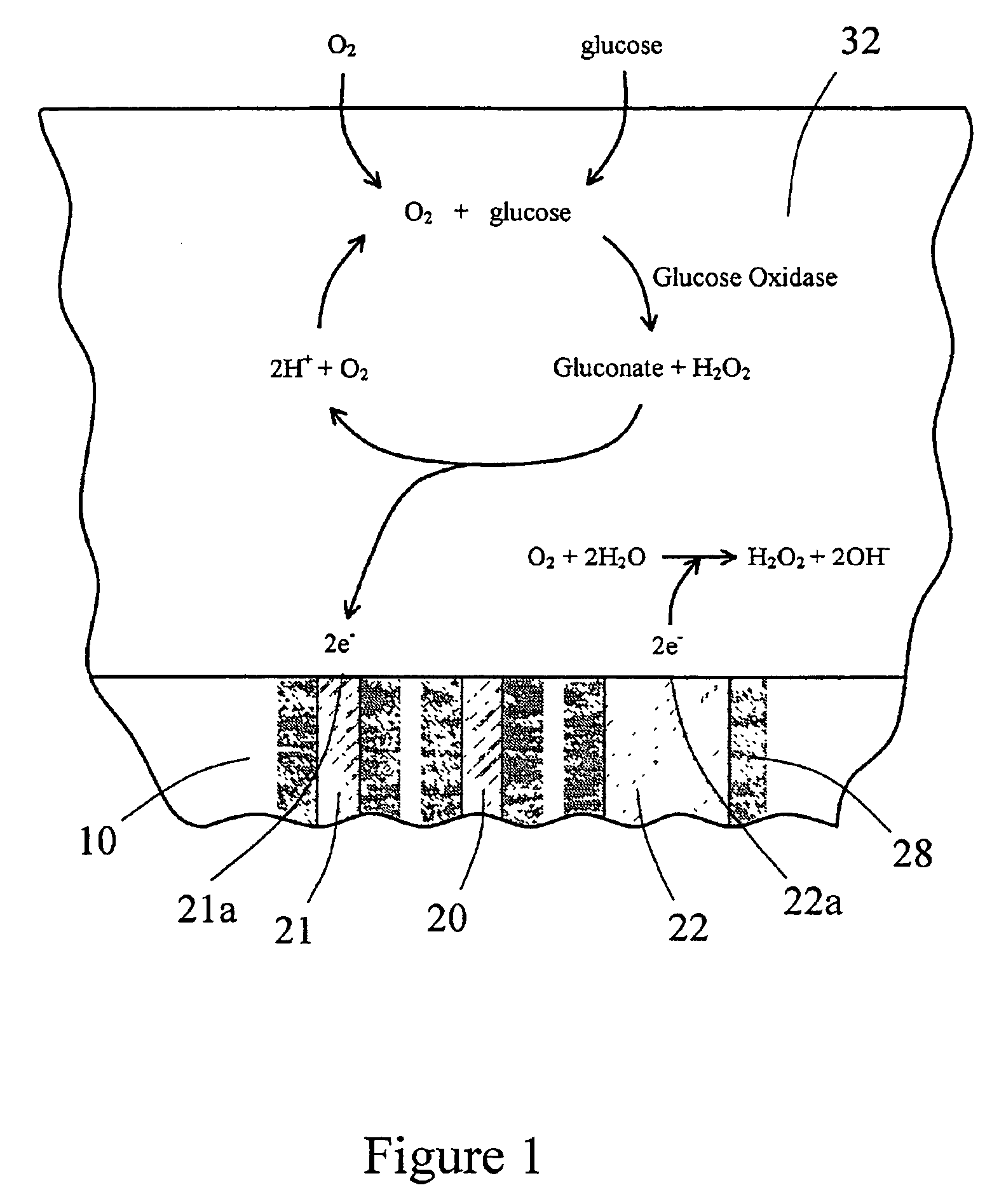
[0027]The term “oxygen antenna domain” and the like refers to a domain composed of a material that has higher oxygen solubility than aqueous media so that it concentrates oxygen from the biological fluid surrounding the biointerface membrane. The domain can then act as an oxygen reservoir during times of minimal oxygen need and has the capacity to provide on demand a higher oxygen gradient to facilitate oxygen transport across the membrane. This enhances function in the enzyme reaction domain and at the counter electrode surface when glucose conversion to hydrogen peroxide in the enzyme domain consumes oxygen from the surrounding domains. Thus, this ability of the oxygen antenna domain to apply a higher flux of oxygen to critical domains when needed improves overall sensor function.

Problems solved by technology

Consequently, oxygen becomes a limiting reactant in the electrochemical reaction and when insufficient oxygen is provided to the sensor, the sensor will be unable to accurately measure glucose concentration.
Those skilled in the art have come to interpret oxygen limitations resulting in depressed function as being a problem of availability of oxygen to the enzyme.
When this occurs, the counter electrode limitation begins to manifest itself as this electrode moves to increasingly negative voltages in the search for reducible species.
When a sufficient supply of reducible species, such as oxygen, are not available, the counter electrode voltage reaches a circuitry limit of −0.6V resulting in compromised sensor function (see FIG. 3).
This reduces the accuracy of the device. FIG. 4 shows a further example of another glucose sensor in which the counter-electrode reaches the circuitry limit.
Again, once the counter electrode reaches −0.6V, the sensitivity and / or signal to noise ratio of the device is compromised.
These data suggest that there may be a limitation of reducible species at the counter electrode, which may limit the sensitivity of the device as the glucose levels increase.
Unfortunately, this approach increases undesirable products that are produced at lower potentials.
This may contribute to additional current resulting in erroneously high glucose concentration readings.
Additionally, at these increasingly negative potentials, the probability of passivating or poisoning the counter electrode greatly increases.
Furthermore, increased current load increases the negative potentials eventually resulting in electrode failure.
However, when the counter electrode reaction is a reduction reaction, as in Blubaugh, the normally present metal oxide layer will be reduced to bare metal over time leaving the surface subject to corrosion, poisoning, and eventual cascade failure.
This problem is magnified when considering the various constituents of the body fluid that the metal casing is exposed to during in vivo use.
To date, there has been no demonstration of long-term performance of such a device with this counter electrode geometry.

Method used


Image

  • Sensor head for use with implantable devices
  • Sensor head for use with implantable devices
  • Sensor head for use with implantable devices

Examples


example 1

Preparation of the Multi-region Membrane

A. Preparation of the First Region

[0111]The cell disruptive domain may be an ePTFE filtration membrane and the cell impermeable domain may then be coated on this domain layer. The cell impermeable domain was prepared by placing approximately 706 gm of dimethylacetamide (DMAC) into a 3 L stainless steel bowl to which a polycarbonateurethane solution (1325 g, Chronoflex AR 25% solids in DMAC and 5100 cp) and polyvinylpyrrolidone (125 g, Plasdone K-90 D) are added. The bowl was then fitted to a planetary mixer with a paddle type blade and the contents were stirred for 1 hour at room temperature. This solution was then coated on the cell disruptive domain by knife edge drawn at a gap of 0.006″ and dried at 60° C. for 24 hours.

[0112]Alternatively, the polyurethane polyvinylpyrrolidone solution prepared above can be coated onto a PET release liner using a knife over roll coating machine. This material is then dried at 305° F. for approximately 2 min...

example 2

In vitro Evaluation of Sensor Devices

[0119]This example describes experiments directed at sensor function of several sensor devices contemplated by the present invention.

[0120]In vitro testing of the sensor devices was accomplished in a manner similar to that previously described. [Gilligan et al., Diabetes Care 17:882-887 (1994)]. Briefly, devices were powered on and placed into a polyethylene container containing phosphate buffer (450 ml, pH 7.30) at 37° C. The container was placed onto a shaker (Lab Line Rotator, model 1314) set to speed 2. The sensors were allowed to equilibrate for at least 30 minutes and their output value recorded. After this time, a glucose solution (9.2 ml of 100 mg / ml glucose in buffer) was added in order to raise the glucose concentration to 200 mg / dl within the container. The sensors were allowed to equilibrate for at least 30 minutes and their output value recorded. Again, a glucose solution (9.4 ml of 100 mg / ml glucose in buffer) was added in order to ...

example 3

The Effect of Varying the Size and Material of the Counter Electrode on Sensor Response and Accuracy

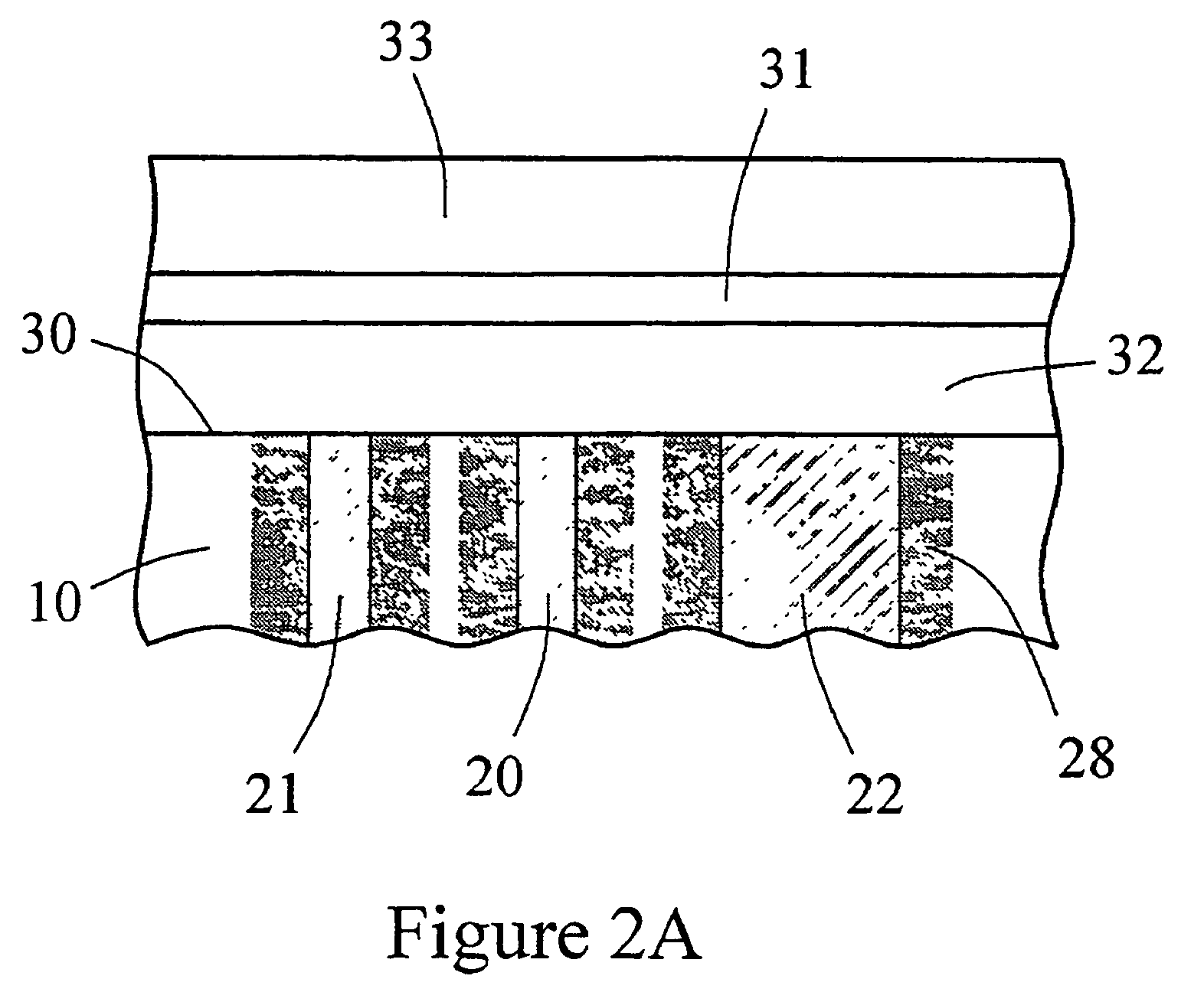
[0125]An in vitro testing procedure used in this example was similar to that described in Example 2. Six devices similar to the one shown in FIGS. 6A and 6B were fitted with the multi-region membrane described herein. Two of these tested devices were comparative devices that possessed Pt counter electrodes having a 0.020″ diameter; this diameter provided for an electrochemically reactive surface of the counter electrode which was substantially equal to the surface area of the working electrode, as schematically shown in FIG. 8. In FIG. 8, the electrode-membrane region includes two distinct regions, the compositions and functions of which have already been described. Region 32 includes an immobilized enzyme. Region 33 includes a cell disruptive domain and a cell impermeable domain. The top ends of electrodes 21 (working), 20 (reference) and 22 (counter) are in contact with an electroly...


PUM

PropertyMeasurementUnit
voltageaaaaaaaaaa
concentrationaaaaaaaaaa
molecular weightaaaaaaaaaa

Abstract

The present invention provides a sensor head for use in an implantable device that measures the concentration of an analyte in a biological fluid which includes: a non-conductive body; a working electrode, a reference electrode and a counter electrode, wherein the electrodes pass through the non-conductive body forming an electrochemically reactive surface at one location on the body and forming an electronic connection at another location on the body, further wherein the electrochemically reactive surface of the counter electrode is greater than the surface area of the working electrode; and a multi-region membrane affixed to the nonconductive body and covering the working electrode, reference electrode and counter electrode. In addition, the present invention provides an implantable device including at least one of the sensor heads of the invention and methods of monitoring glucose levels in a host utilizing the implantable device of the invention.

Description

[0001]This application is a continuation of Ser. No. 09 / 916,711, filed Jul. 27, 2001 now abandoned.FIELD OF THE INVENTION[0002]The present invention relates generally to novel sensor heads utilized with implantable devices, devices including these sensor heads and methods for determining analyte levels using these implantable devices. More particularly, the invention relates to sensor heads, implantable devices including these sensor heads and methods for monitoring glucose levels in a biological fluid using these devices.BACKGROUND OF THE INVENTION[0003]Amperometric electrochemical sensors require a counter electrode to balance the current generated by the species being measured at the working electrode. In the case of a glucose oxidase based glucose sensor, the species being measured at the working electrode is H2O2. Glucose oxidase catalyzes the conversion of oxygen and glucose to hydrogen peroxide and gluconate according to the following reaction:Glucose+O2 →Gluconate+H2O2[0004]...

Claims


Application Information

Patent Timeline
Patent Type & Authority Patents(United States)
IPC IPC(8): A61B5/05A61B5/00G01N27/416A61B5/145A61B5/1473A61B5/1486C12Q1/00G01N27/327
CPCA61B5/14532A61B5/14865C12Q1/002C12Q1/006G01N33/48707G01N33/48785G01N27/3272
Inventor RHODES, RATHBUNTAPSAK, MARK A.BRAUKER, JAMES H.SHULTS, MARK C.
Owner DEXCOM INC
Why Eureka
Try Eureka