Multiphase soft switched DC/DC converter and active control technique for fuel cell ripple current elimination

Active Publication Date: 2009-04-14
VIRGINIA TECH INTPROP INC
View PDF6 Cites 120 Cited by
  • Summary
  • Abstract
  • Description
  • Claims
  • Application Information

AI Technical Summary

Benefits of technology

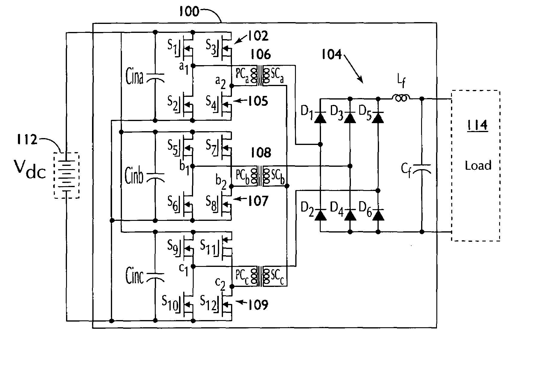
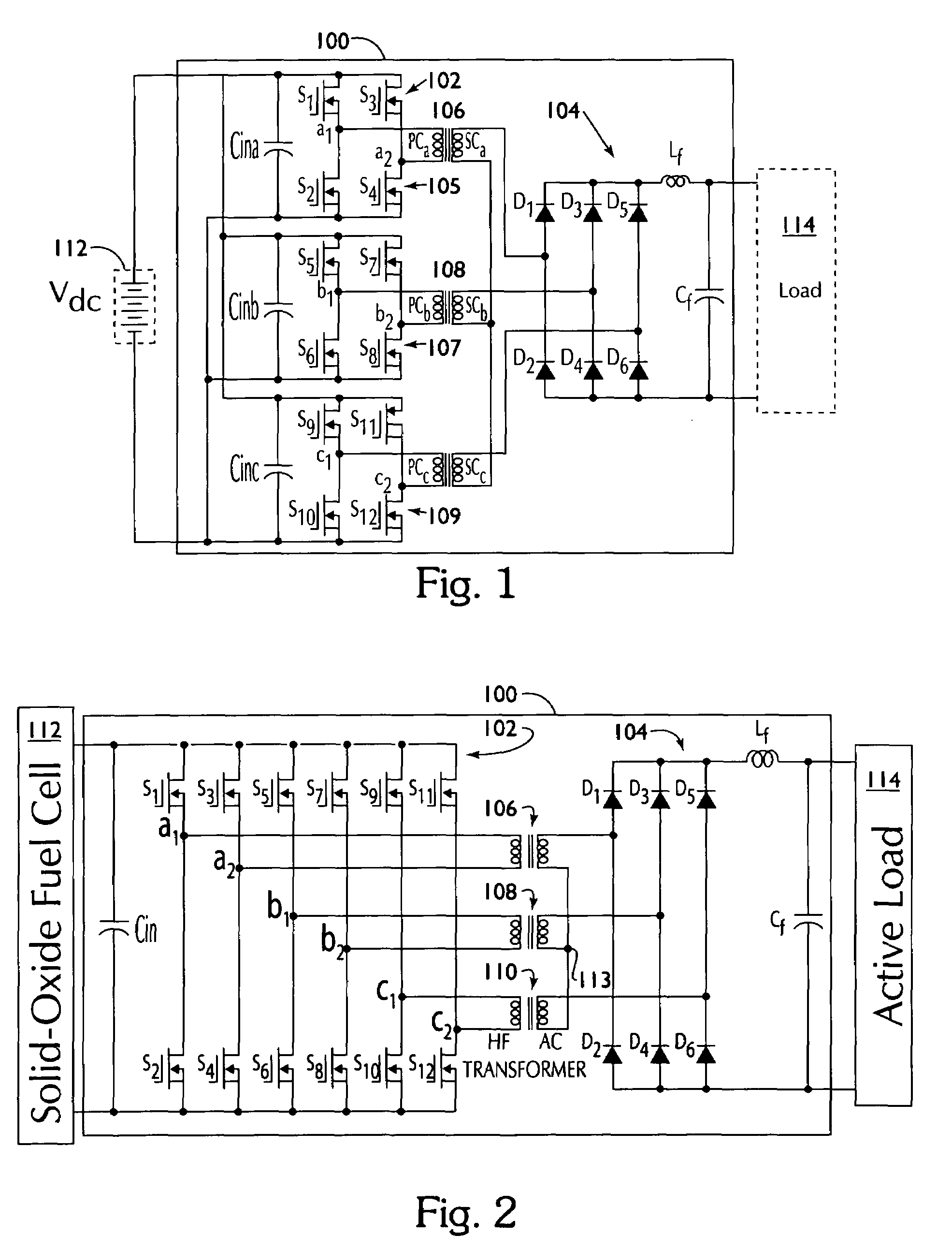
[0033]There are numerous additional features of the converter aspect of the present invention. The output voltage may be doubled while the turns ratio and associated leakage inductance is reduced. There is no or minimal overshoot or ringing on the primary side of the device voltage. DC link inductor current ripple is eliminated. The cost size reduction on the inductor is advantageous. Secondary voltage overshoot is reduced resulting in cost and size reduction with the elimination of voltage clamping. There is significant EMI reduction with an associated reduction of cost pertaining to the EMI filter. Soft switching occurs over a wide load range. High efficiency e

Problems solved by technology

Unfortunately, a fuel cell power system that contains a single phase DC/AC inverter tends to draw an AC ripple current at twice the output frequency.
Such a ripple current may shorten fuel cell life span and worsen the fuel efficiency due to the hysteresis effect.
Additional issues are associated with a DC/DC converter, including cost, efficiency and reliability, as well as ripple current.
Full bridge converters normally utilize large inductors to achieve ZVS, which will cause duty cycle loss and additional power loss during freewheeling.
In such a converter, conduction loss introduced by the high circulating current may sacrifice the efficiency gained by soft switching.
For a

Method used


Image

  • Multiphase soft switched DC/DC converter and active control technique for fuel cell ripple current elimination
  • Multiphase soft switched DC/DC converter and active control technique for fuel cell ripple current elimination
  • Multiphase soft switched DC/DC converter and active control technique for fuel cell ripple current elimination

Examples


case 1

[0117] 0°2) is shifted less than 60° (or ⅙ switching period). The gate signals for the upper devices of all 6 legs are shown in FIG. 5a, the filter inductor current in illustrated in FIG. 5b, and the phase output voltages and rectifier output voltage (or filter input voltage) waveforms are illustrated in FIG. 5c. At most one phase transfers DC bus voltage to the output; thus, the maximum ideal voltage is 0. Consequently, the averaged output voltage is:

[0118]Vout_=α60⁢°·n·Vdc.

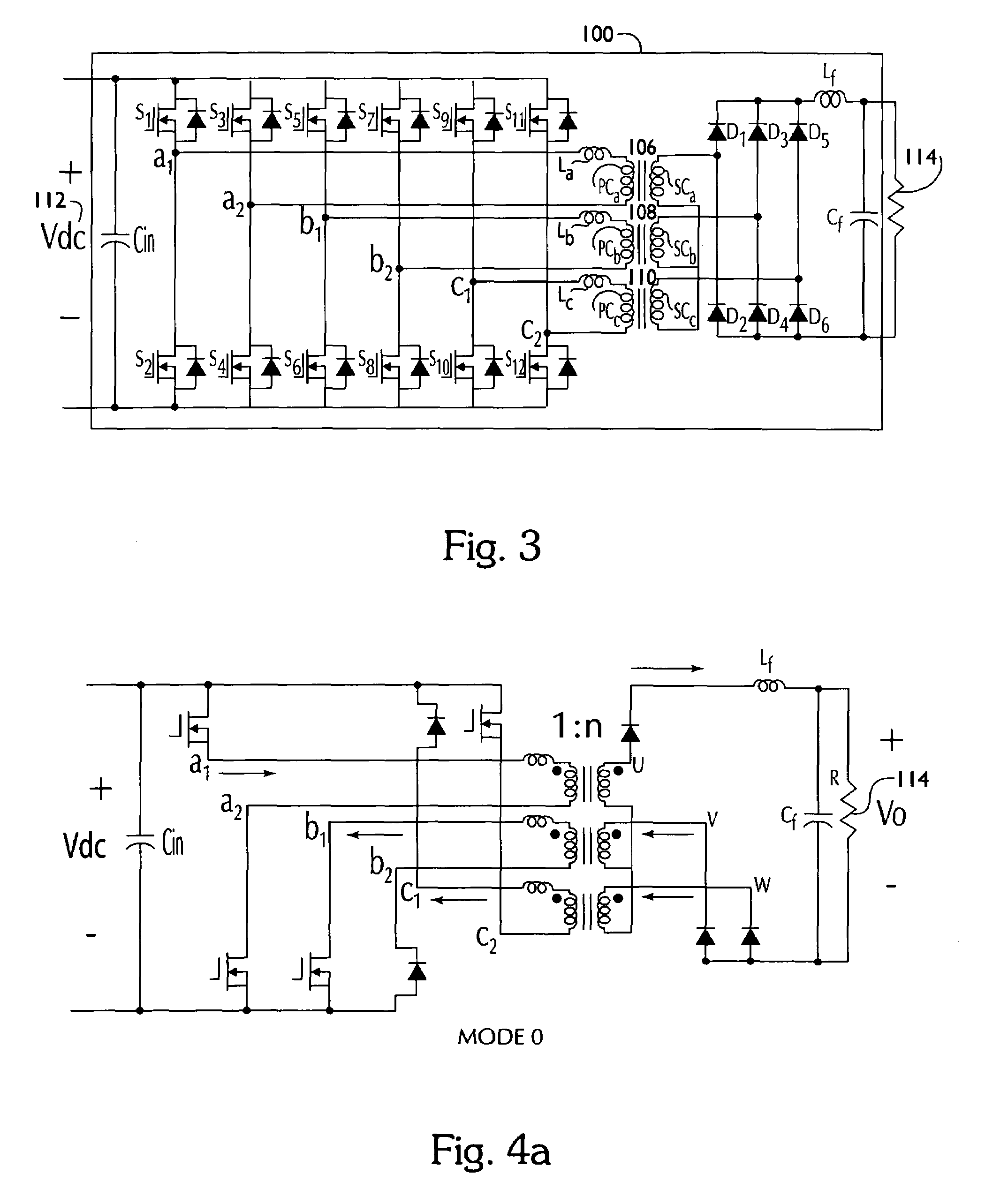
[0119]The gate signals and inductor current waveforms are shown in FIGS. 5a and 5b. FIG. 5a corresponds to the case 1 switch gate signals. Symbol a1p means the upper switch gate signal of phase leg a1. Similarly, a2p, b1p, b2p, c1p and c2p are the upper switch gate signals of phase leg a2, b1, b2, c1 and c2, respectively. From the timing diagram as an example in mode 0, upper switches a1p, c1p, and c2p are turned on, and three lower switches on phase legs a2, b1, and b2 are turned on. Therefore, phase A is suppl...

case 2

[0132] 60°a-6c show the top-switch gate signals and inductor current waveforms for case 2. The voltage across each transformer primary and the resulting voltage at the output of the rectifier are shown in FIG. 6c. FIG. 6a shows the case 2 switch signals, and FIG. 6c shows the transformer primary voltages and rectifier output for case 2.

[0133]In this case, at least one phase and at most two phases transfer dc bus voltage to the output side. Thus, the ideal maximum voltage transferred to the output is 2n·Vdc, and the minimum voltage is n·Vdc. Through similar analysis as in case 1, the durations for this mode are

[0134]Δ⁢⁢t=α-60⁢°60⁢°⁢T

and

[0135]Δ⁢⁢t=120⁢°-α60⁢°⁢T,

respectively. In other words, the output voltage is 2n·Vdc for

[0136]Δ⁢⁢t=α-60⁢°60⁢°⁢T

and n·Vdc for

[0137]Δ⁢⁢t=120⁢°-α60⁢°⁢T.

Therefore, the averaged output voltage can be derived as

[0138]V_out=n·Vdc+α-60⁢°60⁢°·n·Vdc.

Alternatively, the averaged output voltage can be calculated as:

[0139]Vout_=α-60⁢°60⁢°·2⁢n·Vdc+120⁢°-α60⁢°⁢n·Vdc=α6...

case 3

[0140] 120°a-7c shows the upper-switch gate signals and inductor current waveforms for case 3. FIG. 7a shows the switch gate signals for case 3, and FIG. 7c shows the phase output voltages and rectifier output voltage. The voltage across each transformer primary and the resulting voltage at the output of the rectifier are shown in FIG. 7c. Notice how the voltage at the output of the rectifier is constant.

[0141]In this case, at least two phases and at most three phases transfer DC bus voltage to the output side. The output voltage overlaps, thus the ideal voltage transferred to the output is 2n·Vdc at any time, independent of the phase-shift angle α. This also accounts for the filter inductor current being constant for the ideal case. Therefore, the averaged output voltage is uncontrollable and is always equal to Vout=2n·Vdc.

[0142]Since the voltage conversion ratio is fixed, the converter behaves like a transformer, but with DC input / output voltage. Therefore, this mode is defined as...


PUM


Abstract

DC/DC converter has a transformer having primary coils connected to an input side and secondary coils connected to an output side. Each primary coil connects a full-bridge circuit comprising two switches on two legs, the primary coil being connected between the switches on each leg, each full-bridge circuit being connected in parallel wherein each leg is disposed parallel to one another, and the secondary coils connected to a rectifying circuit. An outer loop control circuit that reduces ripple in a voltage reference has a first resistor connected in series with a second resistor connected in series with a first capacitor which are connected in parallel with a second capacitor. An inner loop control circuit that reduces ripple in a current reference has a third resistor connected in series with a fourth resistor connected in series with a third capacitor which are connected in parallel with a fourth capacitor.

Description

RELATED APPLICATIONS[0001]This application claims the benefit of U.S. Provisional Application Ser. No. 60 / 654,332 entitled “Multiphase Softswitched DC to DC Converter” filed on Feb. 18, 2005, the contents of which are incorporated herein by reference in its entirety.STATEMENT REGARDING FEDERALLY SPONSORED RESEARCH OR DEVELOPMENT[0002]This invention was made with government support under contract No. DE-FC26-02NT41567 awarded by the National Energy Technology Laboratory of the U.S. Department of Energy. The U.S. Government has certain rights in the invention.BACKGROUND OF THE INVENTION[0003]As the demand for clean energy sources increases, more research effort is being placed on fuel cells, wind-generation, and photovoltaic energy sources. Fuel cells are expected to be used in a wide variety of applications including stationary electric power plants, motive and auxiliary power for vehicles, and micro-power applications. Fuel cells are considered to be a major contribution to future e...

Claims


Application Information

Patent Timeline
IPC IPC(8): H02M3/335
CPCH02P8/12H02M1/14H02M3/33573H02M3/33571
Inventor LAI, JIH-SHENGLIU, CHANGRONGRIDENOUR, AMY
Owner VIRGINIA TECH INTPROP INC
Why Eureka
Try Eureka