Catalyst composition preparation and use
- Summary
- Abstract
- Description
- Claims
- Application Information
AI Technical Summary
Benefits of technology
Problems solved by technology
Method used
Image

Examples
examples
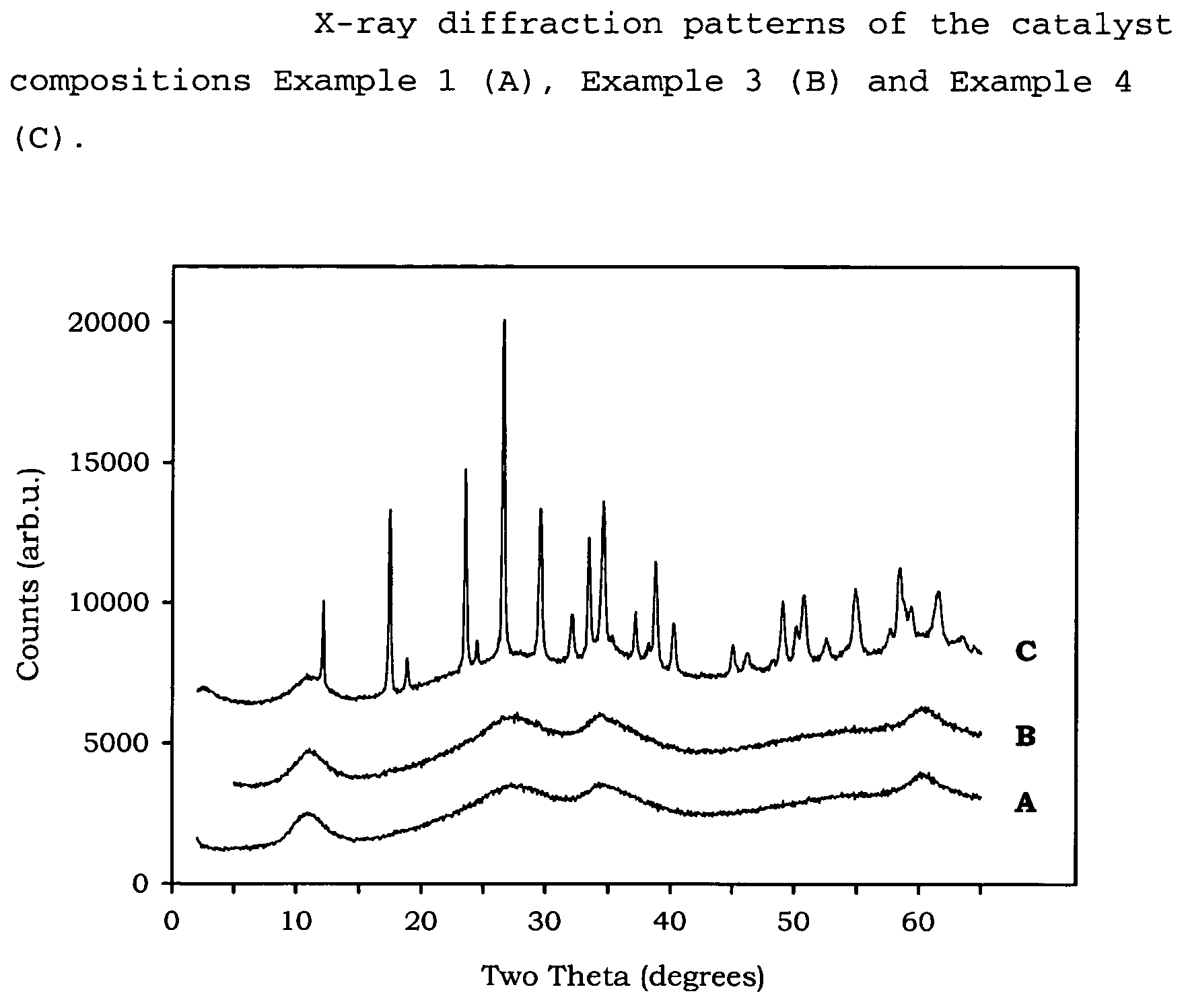
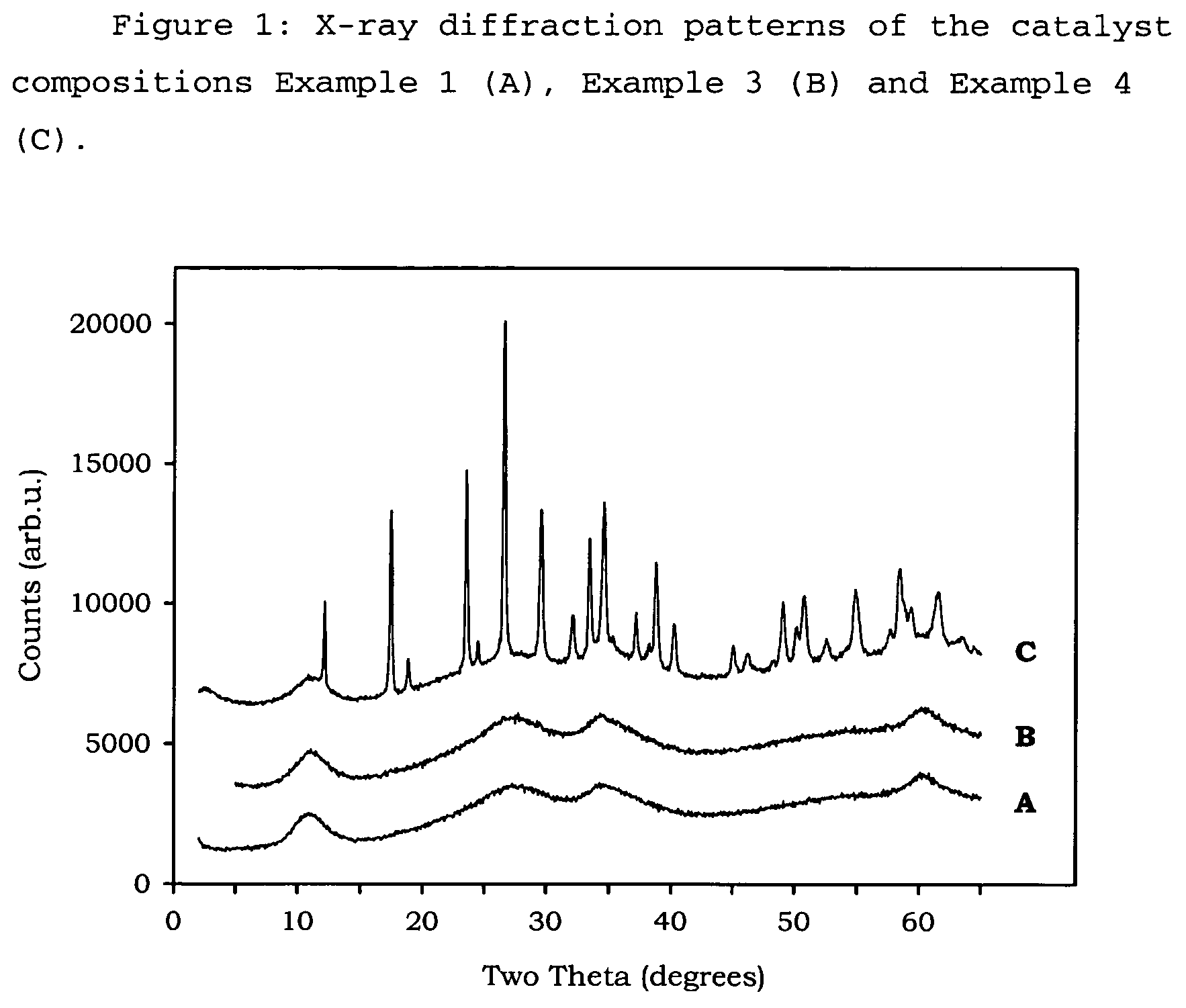
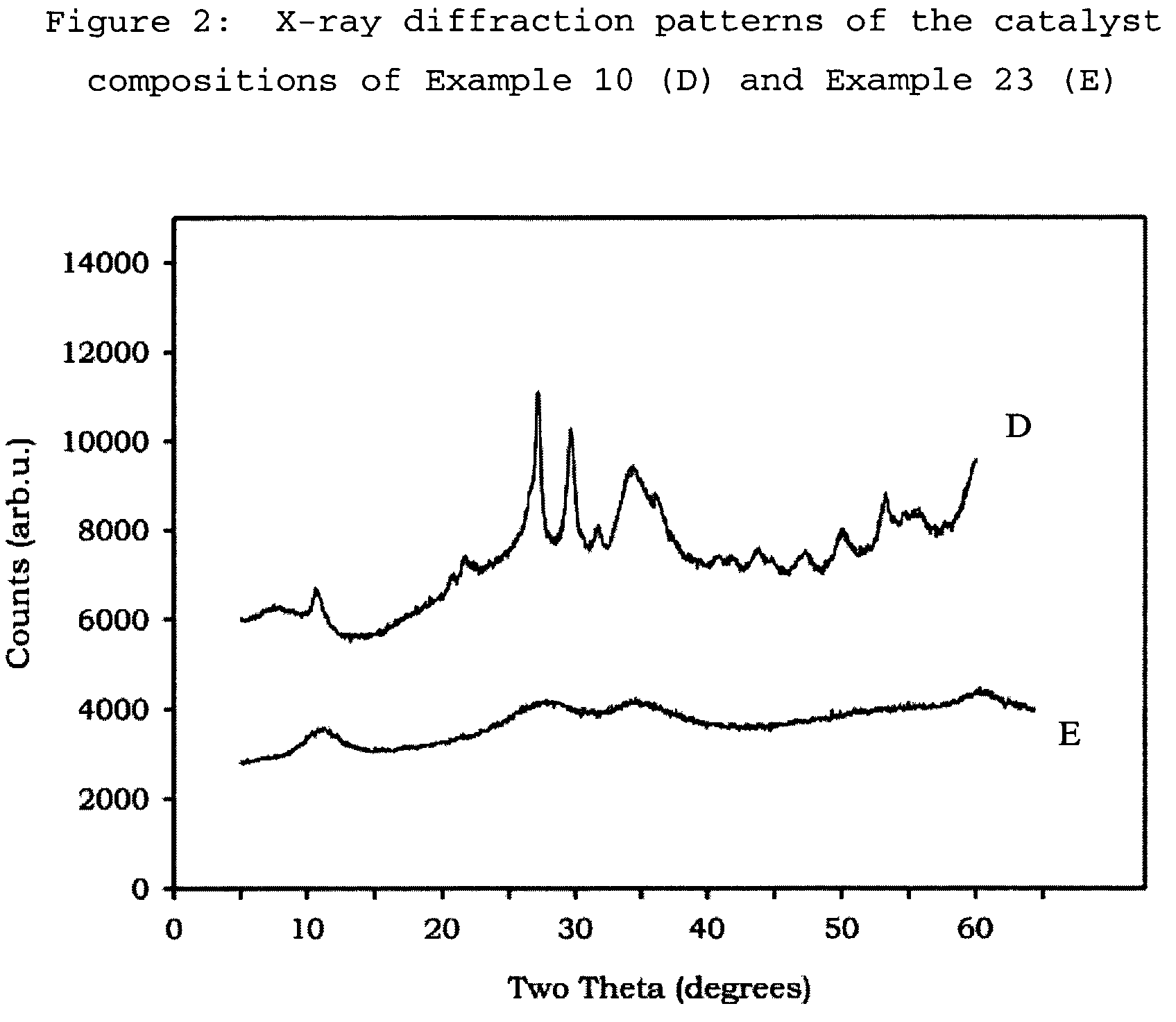
[0097]In these Examples the following test methods have been followed to provide the measurements given[0098]Flat Plate Crush Strength: ASTM D 6175[0099]Porosity: ASTM D 4284 with drying of the sample at 300° C. for 60 minutes prior to measurement, and using mercury intrusion.[0100]B.E.T. Measurement: ASTM D 3663-99, as modified by ISO 9277, with drying of the sample at 300° C. for 60 minutes prior to measurement, and using nitrogen as adsorbate.[0101]Pore volume: obtained from nitrogen adsorption up to 95 nm on the B.E.T. adsorption curve.[0102]XRD analysis: XRD analysis was performed on a Philips PW1800 Bragg-Brentano type powder diffractometer using Cu K-α radiation between 2θ values of 5 to 60 degrees (0.05° resolution with 7 second steps). Where shaped samples were analysed, they were first crushed and pressed and placed into a sample holder (1.5 mm deep).
Examples 1 to 5, and 17 to 22 show the preparation and activity of catalyst compositions made by the metals' slurry preparat...
example 1
[0104]256.1 g ADM (ammonium dimolybdate) having 56.5 wt % Mo, 220.5 g NiCO3 were mixed, and added to 2250 g water in a 5 litre Medimex autoclave, while stirring at 800 rpm. The temperature was increased to approximately 80° C., under pressure. Separately, 113 g ammonia (25 wt % strength), 1.06 mol nitrogen / mol (NiO+MoO3), was diluted with 750 g water in a beaker. 92.2 g Sipernat 50 (a white silica powder with predominantly spherical particles, available from Degussa) was dispersed in this solution. The pressure of the autoclave was released, after which the autoclave was opened and the silica slurry was pumped into the metal-containing slurry. A small amount of water was used to rinse the last part of the silica into the autoclave. The autoclave was closed and the mixture was again heated under pressure to approximately 80° C. with stirring at 700 rpm for 30 minutes. The warm mixture was pumped into a flask and the solids were recovered by means of spray drying, wherein the conditio...
example 2
[0113]The activity of the catalyst prepared in Example 1 for hydrodesulfurization of thiophene in gas phase and also of gas oil feedstocks were evaluated in this Example. Samples of the catalyst were crushed and sieved to 28-80 mesh fraction in order to avoid diffusion limitation during reaction. The catalyst samples were dried at 300° C. for at least 1 hour before loading 0.2 g into a glass reactor. Presulfiding is performed under atmospheric conditions in gas phase (13 vol % H2S in hydrogen), with a ramp of 10° C. / min from room temperature (20° C.) to 270° C., and holding for 30 minutes before raising the temperature to 350° C. again at a rate of 10° C. / min. The HDS reaction of thiophene (6 vol % in hydrogen) is measured every half hour at 350° C.
[0114]Data from 1 hour and 4 hours are reported in Table 2.
[0115]
TABLE 2Thiophene test60 min240 minThiophene conversion39.48%29.84%Hydrogenation14.99%13.82%Hydrog. / thioph. -conv.0.380.46
[0116]Gas oil tests were performed with three feeds ...
PUM
| Property | Measurement | Unit |
|---|---|---|
| Angle | aaaaa | aaaaa |
| Angle | aaaaa | aaaaa |
| Angle | aaaaa | aaaaa |
Abstract
Description
Claims
Application Information
 - R&D
- Intellectual Property
- Life Sciences
- Materials
- Tech Scout
- Unparalleled Data Quality
- Higher Quality Content
- 60% Fewer Hallucinations
Browse by: Latest US Patents, China's latest patents, Technical Efficacy Thesaurus, Application Domain, Technology Topic, Popular Technical Reports.
© 2025 PatSnap. All rights reserved.Legal|Privacy policy|Modern Slavery Act Transparency Statement|Sitemap|About US| Contact US: help@patsnap.com