Light scanning microscope and use

a scanning microscope and light technology, applied in the field ofconfocal laser scanning microscopes, can solve the problems of narrow limits on the capability of confocal raman spectroscopy to record two or three-dimensional microscopic images with high dot density, and low signal intensity,

Active Publication Date: 2009-07-14
CARL ZEISS MICROSCOPY GMBH
View PDF24 Cites 28 Cited by
  • Summary
  • Abstract
  • Description
  • Claims
  • Application Information

AI Technical Summary

Benefits of technology

[0009]The task set forth by the invention is therefore to expand upon a laser scanning microscope in such a manner that it can also record spectroscopic signals that are low in intensity within the shortest possible amount of time.

Problems solved by technology

A problem in Raman spectroscopy consists in that the levels of signal intensity are frequently lower by several orders of magnitude as compared to classical fluorescence spectroscopy.
The periods of measurement resulting from that often span many hours or days, which naturally sets narrow limits on the capabilities of confocal Raman spectroscopy for recording two or three dimensional microscopic images with high dot density.
A reduction in the integration time would theoretically be conceivable by increasing laser output performance, however, this quickly leads to the destruction of the specimen.
One is faced with similar problems in the area on non-linear optical microscopy, which, for example, offers attractive contrasting methods with the second harmonic generation but whose practical application however, is highly limited as well due to the low intensity of the signals and to the long measurement periods associated therewith.
The construction known from the U.S. Pat. No. 6,134,002 achieves an acceleration in image recording speed by shortening the periods of spectral analysis, which is why it forcibly depends on a spectral analyzer with a slit-shaped entrance region serving as a detector, thus it is highly limited with regards to a plurality of possible detectors.

Method used


Image

  • Light scanning microscope and use
  • Light scanning microscope and use
  • Light scanning microscope and use

Examples


Embodiment Construction

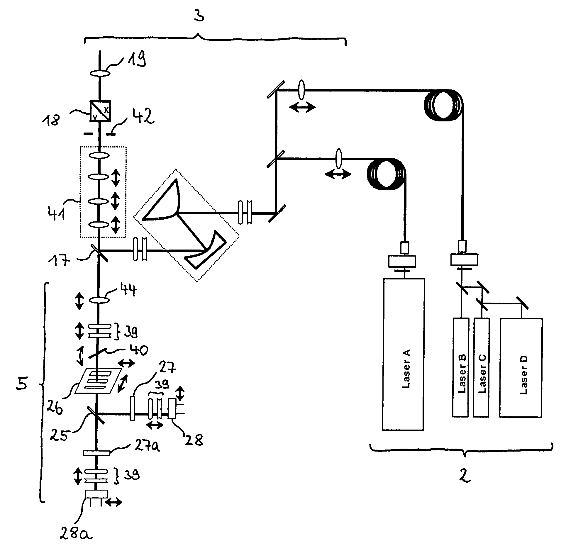
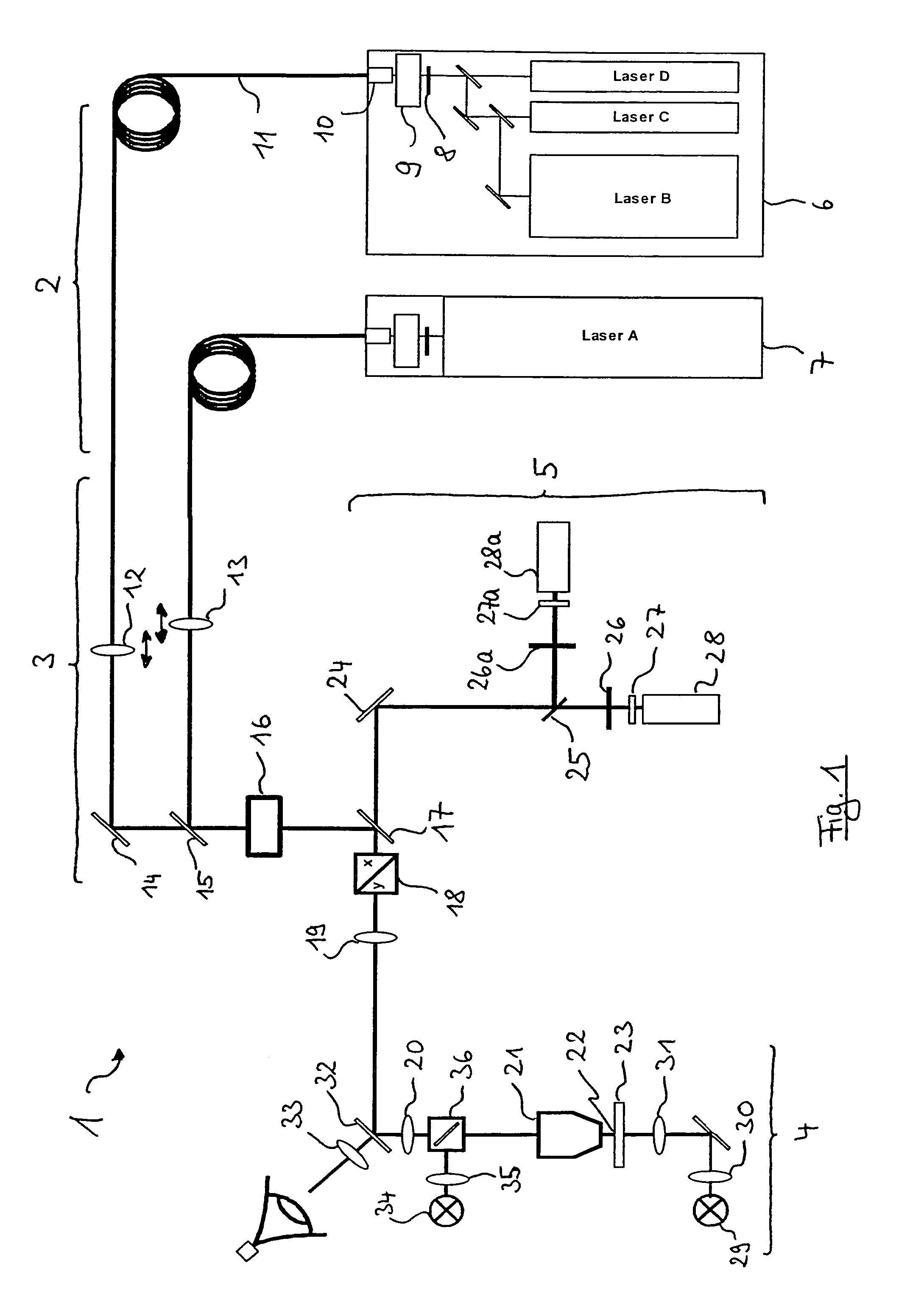
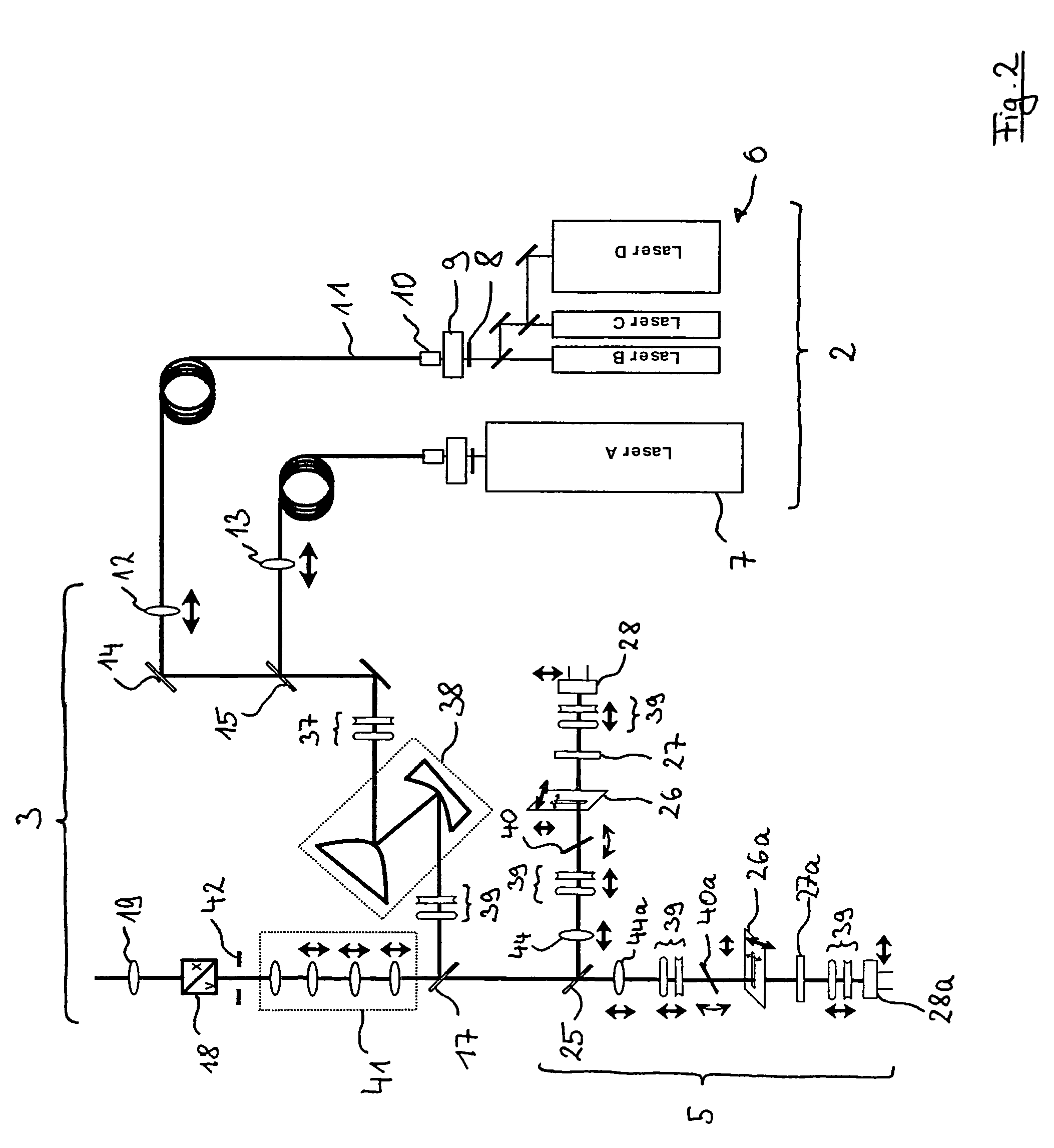
[0108]FIG. 1 schematically shows a laser scanning microscope 1, which is basically comprised of five components: of a beaming source module 2, which generates excitation radiation for laser scanning microscopy, of a scanning module 3, which conditions the excitation radiation and properly deflects it for scanning over a specimen, of a microscope module 4, which directs the scanning beam made available by the scanning module in a microscopic beam path over the specimen, as well as of a detector module 5, which receives radiation and detects optical irradiation from the specimen. The detector module 5 can hereby be spectrally designed to have multiple channels, as represented in FIG. 1.

[0109]The beaming source module 2 generates illuminating radiation, which is suited for laser scanning microscopy, more specifically, radiation which can release fluorescence. Depending on the application, the beaming source module exhibits several sources of radiation to this end. In a represented form...


PUM


Abstract

In a confocal laser scanning microscope with an illuminating configuration (2), which provides an illuminating beam for illuminating a specimen region (23), with a scanning configuration (3, 4), which guides the illuminating beam over the specimen while scanning, and with a detector configuration (5), which via the scanning configuration (3, 4) images the illuminated specimen region (23) by means of a confocal aperture (26) on to at least one detector unit (28), it is provided that the illuminating configuration (2) of the scanning configuration (3, 4) provides a line-shaped illuminating beam, that the scanning configuration (3, 4) guides the line-shaped illuminating beam over the specimen f while scanning and that the confocal aperture is designed as a slit aperture (26) or as a slit-shaped region (28, 48) of the detector unit (28) acting as a confocal aperture.

Description

BACKGROUND OF THE INVENTION[0001]1. Field of the Invention[0002]The invention relates to a confocal laser scanning microscope with an illuminating configuration, which provides an illuminating beam for illuminating a specimen region, with a scanning configuration, which guides the illuminating beam over the specimen while scanning, and with a detector configuration, which via the scanning configuration images the illuminated specimen region by means of a confocal aperture on to at least one detector unit.[0003]2. Related Art[0004]Confocal laser scanning microscopes of the type initially mentioned are known in the state of the art, for example, let us cite the German patent DE 197 02 753 A1 in reference thereto. Most recently, components and technical systems from microscopy, specifically from confocal imaging laser scanning microscopes, have been ever more frequently applied to spectroscopic imaging techniques. In this manner, it is possible to survey the spectroscopic characteristi...

Claims


Application Information

Patent Timeline
Patent Type & Authority Patents(United States)
IPC IPC(8): G02B21/00G02B21/06G01J3/02G01J3/06G01J3/10G01J3/12G01J3/44
CPCG01J3/02G01J3/0202G01J3/021G01J3/0227G01J3/0237G02B21/008G01J3/10G01J3/44G02B21/0044G02B21/0064G01J3/06G01J2003/1217
Inventor FUNK, JOERG-MICHAELWOLLESCHENSKY, RALFSTEINERT, JOERG
Owner CARL ZEISS MICROSCOPY GMBH
Why Eureka
Try Eureka