
Ion chromatography system with flow-delay eluent recycle

a technology of chromatography and eluent, which is applied in the direction of ion exchangers, separation processes, instruments, etc., can solve the problems of easy contamination of carbonate, easy naoh solution dilute, and laborious off-line preparation of chromatographic eluents

Active Publication Date: 2009-09-08
DIONEX CORP
View PDF8 Cites 16 Cited by
  • Summary
  • Abstract
  • Description
  • Claims
  • Application Information

AI Technical Summary

Benefits of technology

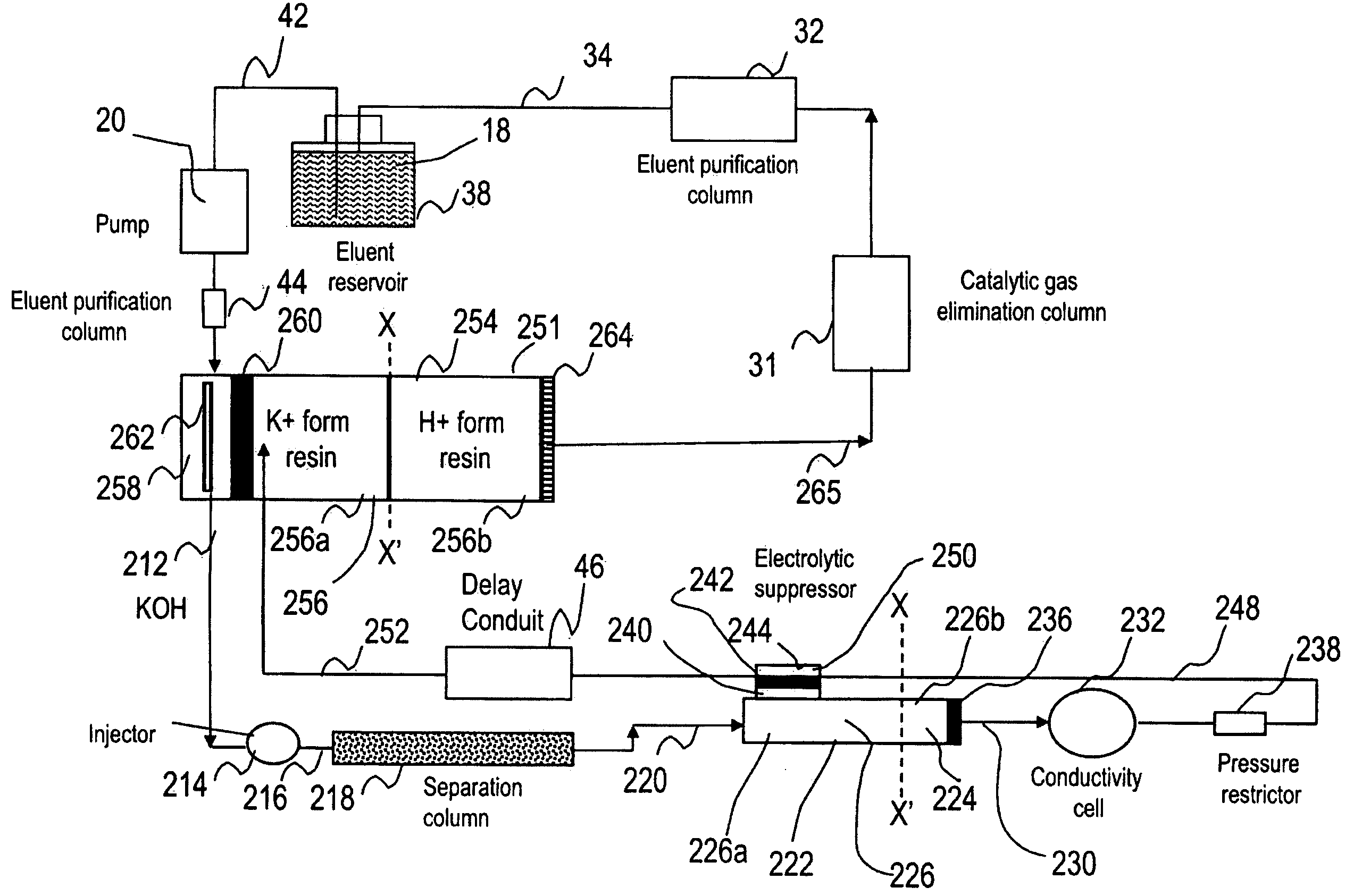
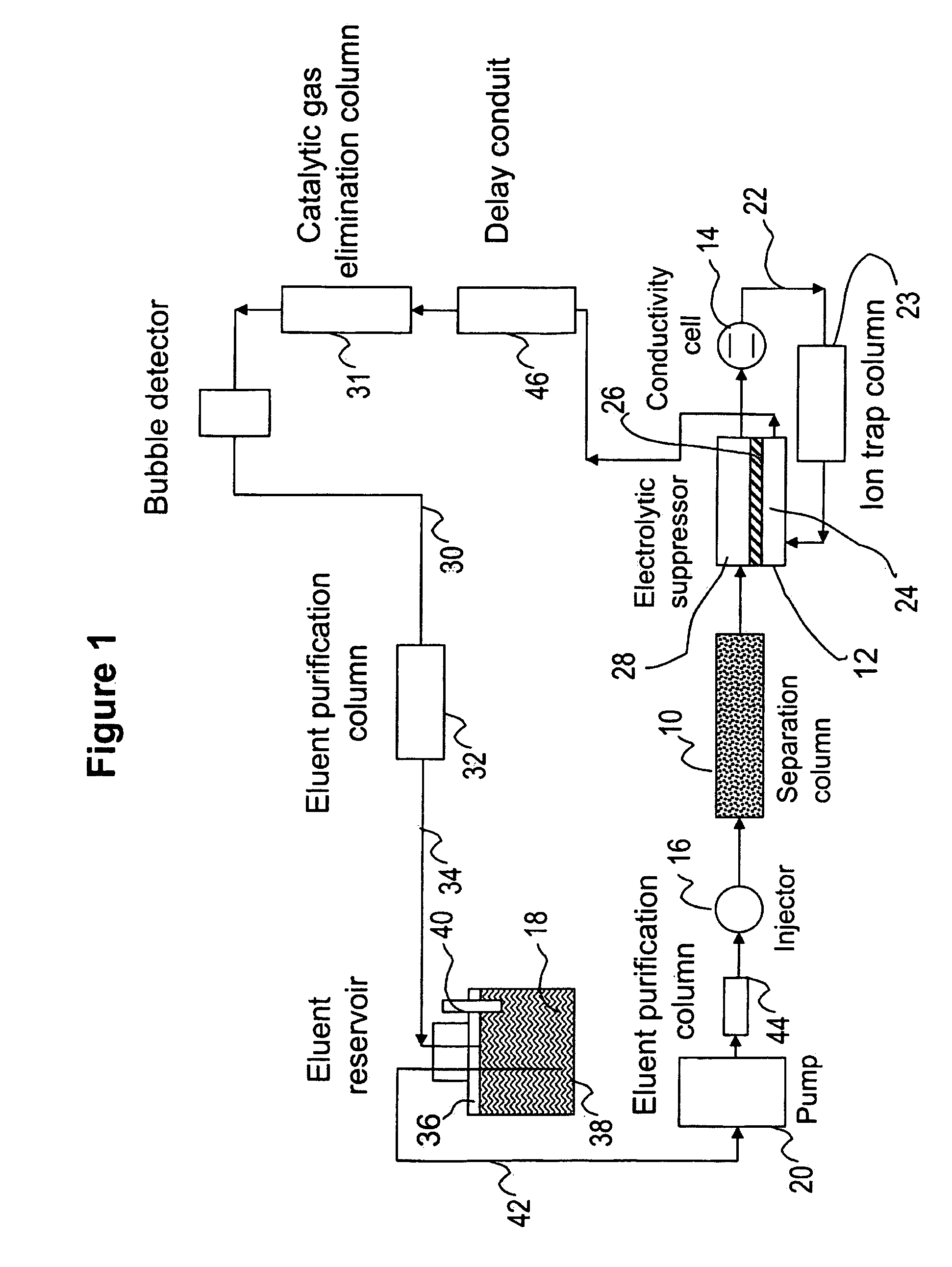
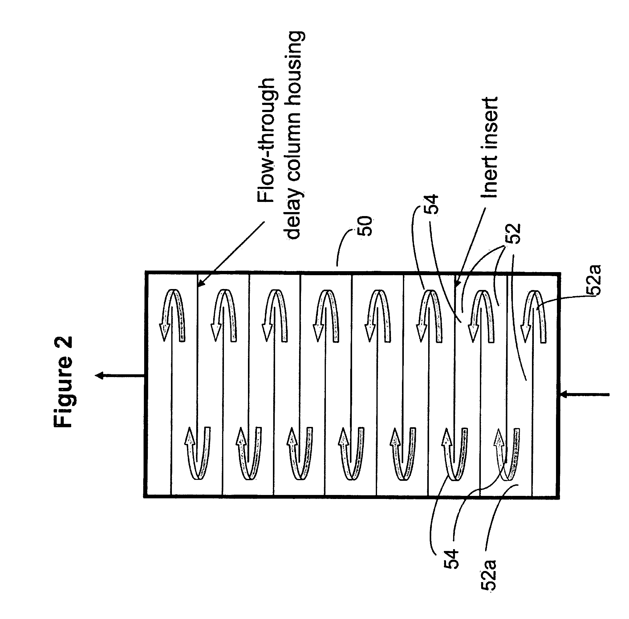
[0005]In one embodiment of the invention, a chromatographic method is provided including the steps of (a) injecting sample ionic species into an aqueous eluent stream from an eluent source, (b) chromatographically separating the sample ionic species in the eluent stream by flowing the same through chromatographic separation medium to exit as a chromatography effluent, (c) flowing the chromatography effluent through a detector to detect the separated sample ionic species in the chromatography effluent to exit as a detector effluent stream, (d) catalytically combining hydrogen and oxygen gases or catalytically decomposing hydrogen peroxide, or both, in the detector effluent stream by flowing it through a catalytic gas elimination chamber, to form water and reduce the gas content of the eluent effluent stream exiting the gas elimination chamber, and (e) recycling the catalytic gas elimination chamber effluent stream from the catalytic gas elimination chamber to the chromatography separation column, the residence time for flow of the detector effluent stream between the detector and the catalytic gas elimination chamber being at least about one minute to facilitate decomposition of unstable oxidative compounds.

Problems solved by technology

Off-line preparation of chromatographic eluents can be tedious and prone to operator errors, and often introduces contaminants.
For example, dilute NaOH solutions, widely used as the electrolytes in eluents in the ion chromatographic separation of anions, are easily contaminated by carbonate.
The preparation of carbonate-free NaOH eluents is difficult because carbonate can be introduced as an impurity from the reagents or by adsorption of carbon dioxide from air.
The presence of carbonate in NaOH eluents often compromises the performance of an ion chromatographic method, and can cause an undesirable chromatographic baseline drift during the hydroxide gradient and even irreproducible retention times of target analytes.
The continuous operation of an ion chromatography system can consume a significant amount of eluents.
The consistent preparation of such large amount of the eluent as well as the disposal of the used eluent can pose serious logistical challenges to the system operators in terms of costs and labor, especially in cases where unattended or less frequently attended operations are required.
Even though it overcomes a number of issues associated conventional approaches of eluent preparation in ion chromatography, the use of on-line electrolytic eluent generation devices still requires a constant supply of high purity water from an external source for continuous operation and waste disposal issue remains.

Method used


Image

  • Ion chromatography system with flow-delay eluent recycle
  • Ion chromatography system with flow-delay eluent recycle
  • Ion chromatography system with flow-delay eluent recycle

Examples


example 4

[0111] A 10 um resin (Ethylvinylbenzene 55% cross linked with divinylbenzene) was used as the substrate in this experiment. The resin was coated with a) 4000 mg / L Tetraammineplatinum (II) Chloride solution 2) 4000 mg / L Diamminepalladium (II) nitrite solution and 3) A combination of 1) and 2) at a concentration of 2000 mg / L each. The resin synthesis protocol followed the outline listed above in example 3. Three standard chromatography guard columns from Dionex Corporation with a 9×50 mm dimensions were packed with the above coated resins using DI water as the packing media.

[0112]The columns were tested for peroxide removal using a DX600 IC system with an electrochemical detector from Dionex Corporation, Sunnyvale, Calif. A CP PA20 column was used with an eluent comprising 100 nM NaOH at 0.5 ml / min flow rate and at 30° C. A gold electrode was used as the electrode and detection was pursued with a pre-loaded quadruple waveform with AgCl reference electrodes. A 10 μL injection sample lo...

example 6

[0115] FIG. 12 shows bubble removal comparison between the three tested columns. Bubbles here are detected as negative spikes of the voltage signal. The more the number of bubbles detected the poorer the catalyst function. Trace A, B & C display the performance of the three catalyst resins as discussed previously in Example 5. Excellent bubble removal is seen with a combination of Platinum and Palladium coated resin.

[0116]Example 7. Since the bubbles were not completely removed we investigated another resin for this application. This is a polystyrene divinylbenzene based proprietary resin from Dionex Corporation (Sunnyvale, Calif.) that was 2% cross-linked and had a diameter of 15.4 micron. This resin was coated with the three combinations as discussed above following the protocol described in Example 3. The peroxide removal is shown in FIG. 13 and shows once again the combination (trace C) outperforming the single metal coated resins. The results are summarized in Table 2 below.

[01...


PUM

PropertyMeasurementUnit
pHaaaaaaaaaa
temperatureaaaaaaaaaa
pHaaaaaaaaaa

Abstract

A chromatographic method including chromatographically separating sample ionic species in an eluent stream, detecting the separated sample ionic species, catalytically combining hydrogen and oxygen gases or catalytically decomposing hydrogen peroxide in a catalytic gas elimination chamber, and recycling the effluent stream from the chamber to the chromatography separation column. The residence time between the detector and the chamber is at least about one minute. Also, flowing the recycle sequentially through two detector effluent flow channels of an electrolytic membrane suppressor. Also, applying heat or UV energy between the detector and the chamber. Also, detecting bubbles after the chamber. Also, a Platinum group metal catalyst and ion exchange medium in the chamber. Apparatus for performing the methods.

Description

BACKGROUND OF THE INVENTION[0001]Since it was introduced in 1975, ion chromatography has become a widely used analytical technique for the determination of anionic and cationic analytes in various sample matrices. In ion chromatography, dilute solutions of acids, bases, or salts are commonly used as the electrolytes in chromatographic eluents.[0002]Traditionally, these eluents are prepared off-line by dilution with reagent-grade chemicals. Off-line preparation of chromatographic eluents can be tedious and prone to operator errors, and often introduces contaminants. For example, dilute NaOH solutions, widely used as the electrolytes in eluents in the ion chromatographic separation of anions, are easily contaminated by carbonate. The preparation of carbonate-free NaOH eluents is difficult because carbonate can be introduced as an impurity from the reagents or by adsorption of carbon dioxide from air. The presence of carbonate in NaOH eluents often compromises the performance of an ion...

Claims


Application Information

Patent Timeline
Patent Type & Authority Patents(United States)
IPC IPC(8): G01N30/02
CPCG01N30/26B01D15/10G01N30/96G01N2030/965
Inventor LIU, YANSRINIVASAN, KANNANPOHL, CHRISTOPHER A.BHARDWAJ, SHEETALLU, ZHONGQING
Owner DIONEX CORP
Learn More