Hybrid fiber coupled artificial compound eye

a compound eye and fiber technology, applied in the field of wide angle imaging systems, can solve the problems of limited field of view, large size of lens, and inability to adjust the focus of image objects, so as to increase the diameter of lenslet arrays, increase the throughput of hybrid arrays, and increase the effect of lenslet diameters

Inactive Publication Date: 2009-09-08
SPECTRAL IMAGING LAB
View PDF15 Cites 71 Cited by
  • Summary
  • Abstract
  • Description
  • Claims
  • Application Information

AI Technical Summary

Benefits of technology

[0021]In accordance with the present invention, there is provided a hybrid multiple aperture array imaging system formed from superposition and apposition compound refractive optics. It combines the high sensitivity attribute of superposition arrays with the high resolution attribute of an apposition array to generate a single, contiguous image. In the superposition section of the optics, a convex shaped array of Keplerian telescope objectives divides and focuses the incoming light into a series of beams that are channeled through the tubes (or hollow light conduits) of a louver baffle. The baffle is terminated by a field stop array that separates the focused light into intermediate sub-images. The size and shape of the sub-images are determined by the size and shape of the field stops. Positioned immediately after the field stops is a convex shaped array of field lenslets that reverses the field angles of the beams. The Keplerian reversal of the beam angles ensures that the final sub-images are upright and orientated properly, so as a composite they form a single, upright image. The superposition effect of the two lenslet arrays works with the field stops to allow the lenslet diameters to be increased without generating the multiple, overlapping and reversed images that would be formed in an apposition array with over sized lenslets. As a consequence, the lenslet diameters of the hybrid can be increased by an order of magnitude over what they would be for either an apposition or superposition array. This increases the throughput of the hybrid array while simplifying manufacturing and alignment.

Problems solved by technology

Single aperture optics have the advantage of good spatial resolution and efficient light capture, but they are disadvantaged by their relatively large size and limited field of view.
The additional optical elements yield a lens that is expensive, heavy, and long.
Another disadvantage of the high resolution, single aperture lens is its need for focus adjustment to image objects at different distances.
As with all such auto focusing schemes, it cannot overcome the inherent design limitation of a single aperture lens: objects at different depths of field cannot be brought into focus simultaneously.
However, the flat design attribute limits the field of view to just 21 degrees.
Unfortunately, the design requires a convex shaped detector array of extremely small size to capture the image.
However, if the lenslets are to be manufactured by hot press molding, then there are practical limits imposed on the minimum lenslet diameter and on the alignment accuracy between the two arrays.
This causes blurring of the image.
Though the afocal optical aberrations can be corrected by introducing more lenslets arrays and different glass types, it is difficult to accomplish this in a superposition architecture, especially with regard to lenslet alignment if the lenslet diameters are very small.
Since the sub-images are inverted, a coherent image can only be constructed by post-processing; reconstruction cannot be accomplished where the sub-images overlap on the detector array.

Method used


Image

  • Hybrid fiber coupled artificial compound eye
  • Hybrid fiber coupled artificial compound eye
  • Hybrid fiber coupled artificial compound eye

Examples


Embodiment Construction

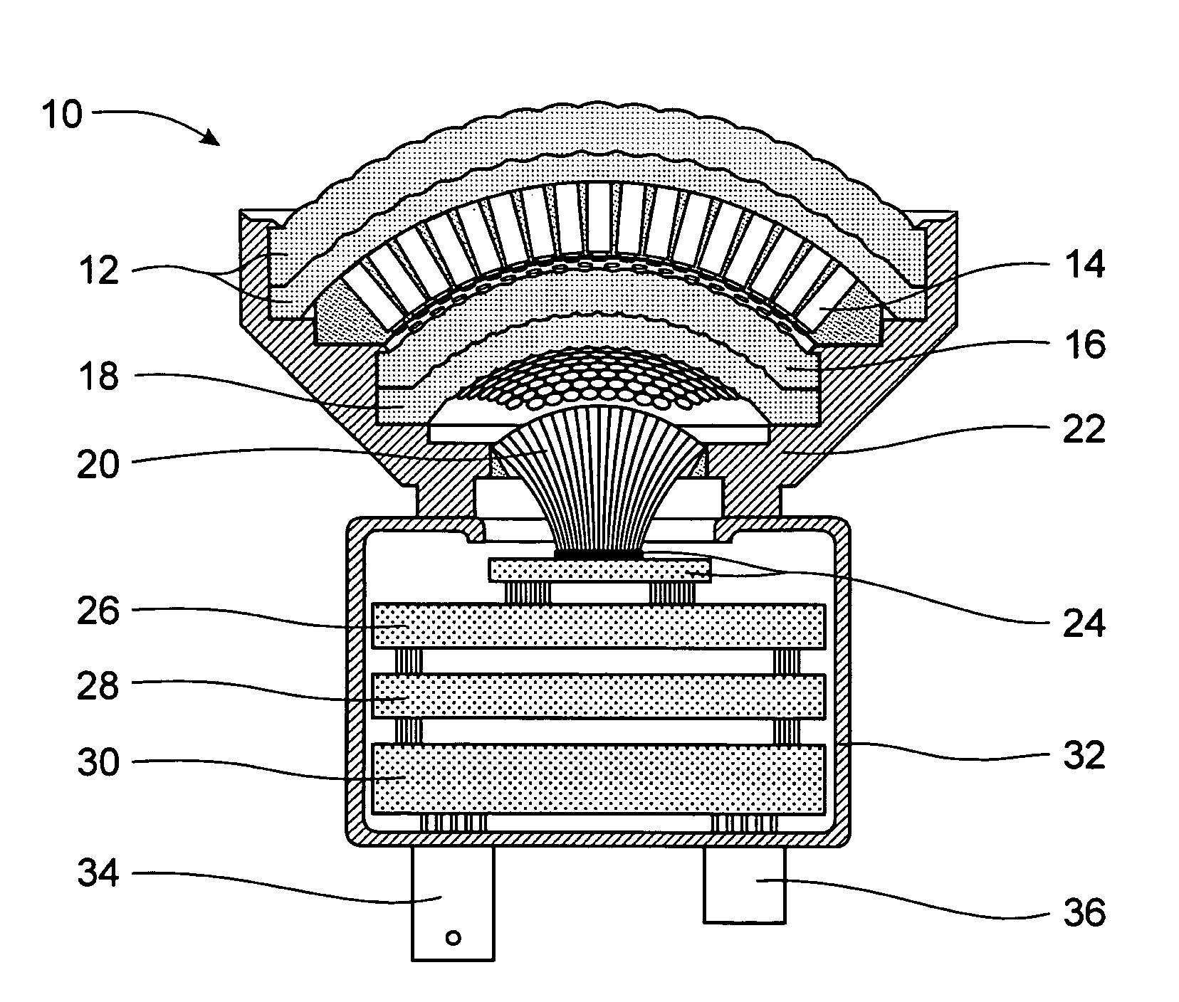
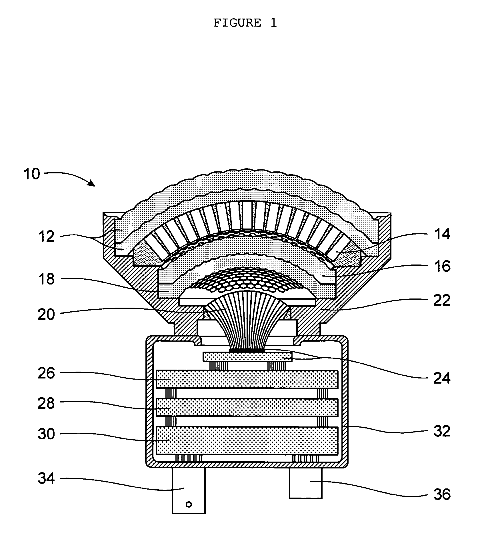
[0041]Referring now to the drawings, FIG. 1 is a cross-sectional view of a hybrid superposition-apposition array imaging system 10, the preferred embodiment of the hybrid fiber coupled artificial compound eye invention. It includes an objective lenslet superposition array 12, a louver baffle 14, a field lenslet superposition array 16, and an erector lenslet apposition array 18, all held rigidly in alignment by an optical mounting structure 22. Each lenslet array is shaped conformally to a positive meniscus base with curvatures that are concentric. Likewise, the louver baffle 14 is shaped into a positive meniscus form that is concentric to the base curvatures of the lenslet arrays. The convex surface of the baffle conforms exactly to the concave surface of the objective superposition array to which it is in contact.

[0042]Attached to the optical mounting structure 22 is the electronics mounting structure 32, which supports a fiber optic imaging taper 20 and a mosaic detector array wit...


PUM


Abstract

A hybrid, wide angle imaging system combines high sensitivity superposition arrays with a high resolution apposition array to generate distortion free images with an infinite depth of field. A conformal, superposition array of Keplerian telescope objectives focuses multiple apertures of light through the tubes of a louver baffle. The baffle tubes are terminated by field stops that separate the focused light into inverted, intermediate sub-images. A superposition array of field lenses, positioned immediately after the field stops, reverses the angles of the light beams. An apposition array of erector lenses, linked optically to the superposition arrays and field stops, refocuses and adjoins the beams into a single, upright image. The upright image is formed on the convex surface of a fiber optic imaging taper, which transfers the image to the flat bottom of the taper where it can be viewed through an eyepiece or digitized by a detector array.

Description

FIELD OF THE INVENTION[0001]The present invention relates to wide angle imaging systems and, more particularly, to high resolution multiple aperture wide angle imaging systems with curved lenslet arrays that can be shaped to conform to a particular surface geometry.BACKGROUND OF THE INVENTION[0002]Conventional camera optics are derived from the eyes of vertebrates, wherein a single lens system captures light through a large aperture and focuses it onto a concave retina. Single aperture optics have the advantage of good spatial resolution and efficient light capture, but they are disadvantaged by their relatively large size and limited field of view. Vertebrates evolved to overcome the field of view limitation by gimbaling the eye in its socket, and by restricting the high resolution capability to the fovea centralis. Camera developers have attempted to extend the high resolution capability beyond the fovea by introducing additional optical elements to reduce the distortion that resu...

Claims


Application Information

Patent Timeline
Patent Type & Authority Patents(United States)
IPC IPC(8): G02B6/26
CPCG02B3/0037G02B6/06H04N5/2254G02B13/06H04N5/33H04N23/55
Inventor REININGER, FRANCIS MARK
Owner SPECTRAL IMAGING LAB
Why Eureka
Try Eureka