Thermoelectric temperature control for extracorporeal blood circuit

a technology of extracorporeal blood and temperature control, which is applied in the direction of dental surgery, teeth capping, lighting and heating apparatus, etc., can solve the problems of large volume of blood within, use of ice baths, and significant use of pumps and conduits for carrying heat exchange fluid, so as to reduce equipment size, reduce blood volume, and increase efficiency

Active Publication Date: 2009-09-15
TERUMO CARDIOVASCULAR SYST CORP
View PDF29 Cites 45 Cited by
  • Summary
  • Abstract
  • Description
  • Claims
  • Application Information

AI Technical Summary

Benefits of technology

[0010]The present invention utilizes a waterless heat exchange system employing a novel heat exchange cassette and a thermoelectric heater / cooler element to achieve advantages of increased efficiency, reduced blood volume, reduced equipment size, increased safety, reduced power requirements, and increased reliability. The waterless thermoelectric device is small enough to fit on an APS1 base, a pole, or the surgical table. It provides large heating and cooling capabilities, substantially instantaneous change of temperature with no moving parts, and operates at low voltage DC.

Problems solved by technology

Lower efficiency results in a larger heat exchanger and, consequently, a greater volume of blood is present within it.
Furthermore, the use of an ice bath and the pumps and conduits for carrying the heat exchange fluid are significant.
Due to the large size of the equipment, it is not easily integrated with other operating room equipment.
Because of the presence of the high voltage, safety measures to protect the patient and the users of the equipment must be taken which add expense to the equipment.
Furthermore, the power requirements may exceed the available power from typical convenience outlets.
The use of purified water as a heat exchange fluid has associated maintenance requirements due to the potential for water induced corrosion and bacterial growth.
The constant maintenance is costly and troublesome.

Method used


Image

  • Thermoelectric temperature control for extracorporeal blood circuit
  • Thermoelectric temperature control for extracorporeal blood circuit
  • Thermoelectric temperature control for extracorporeal blood circuit

Examples


Embodiment Construction

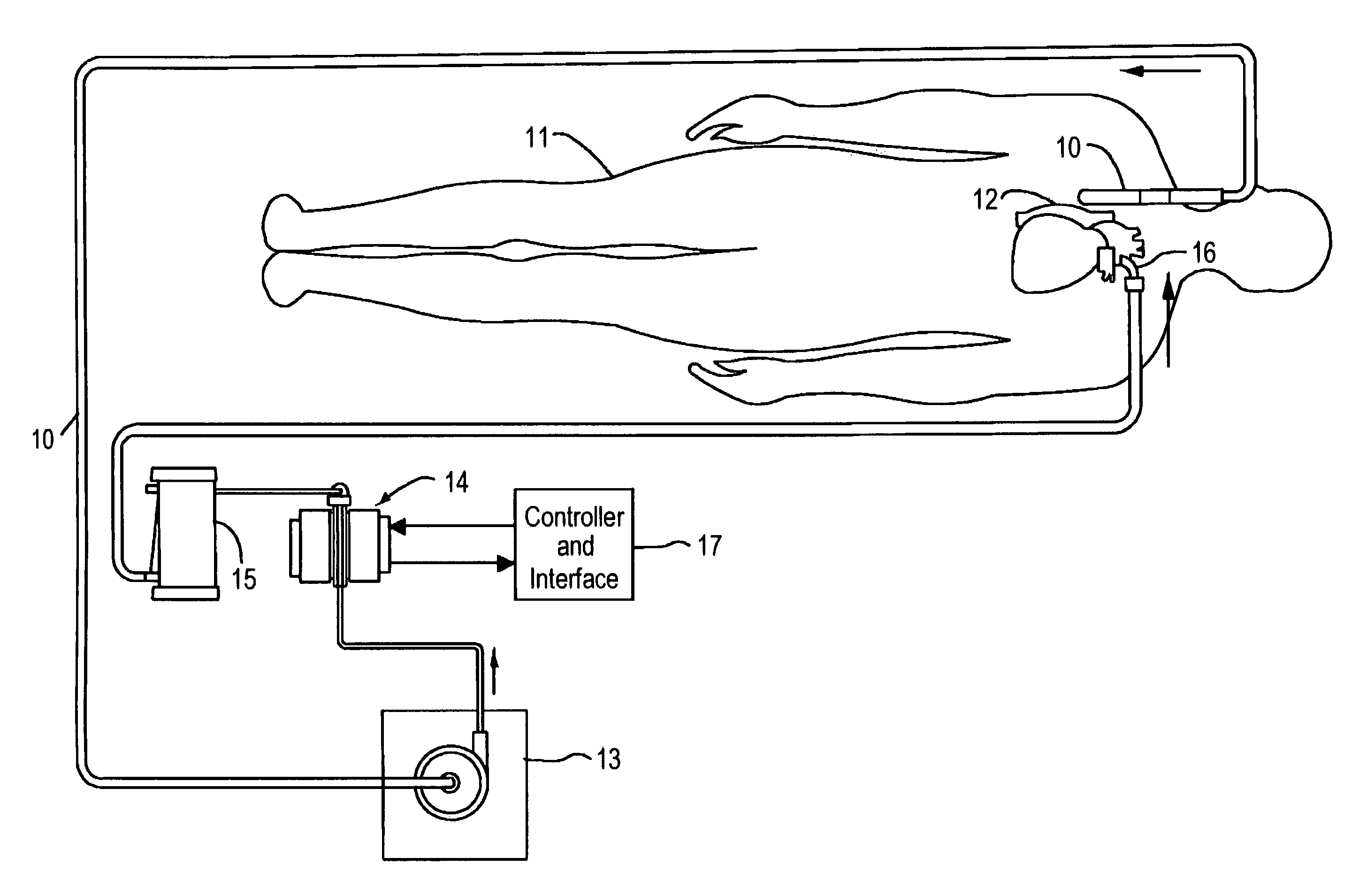
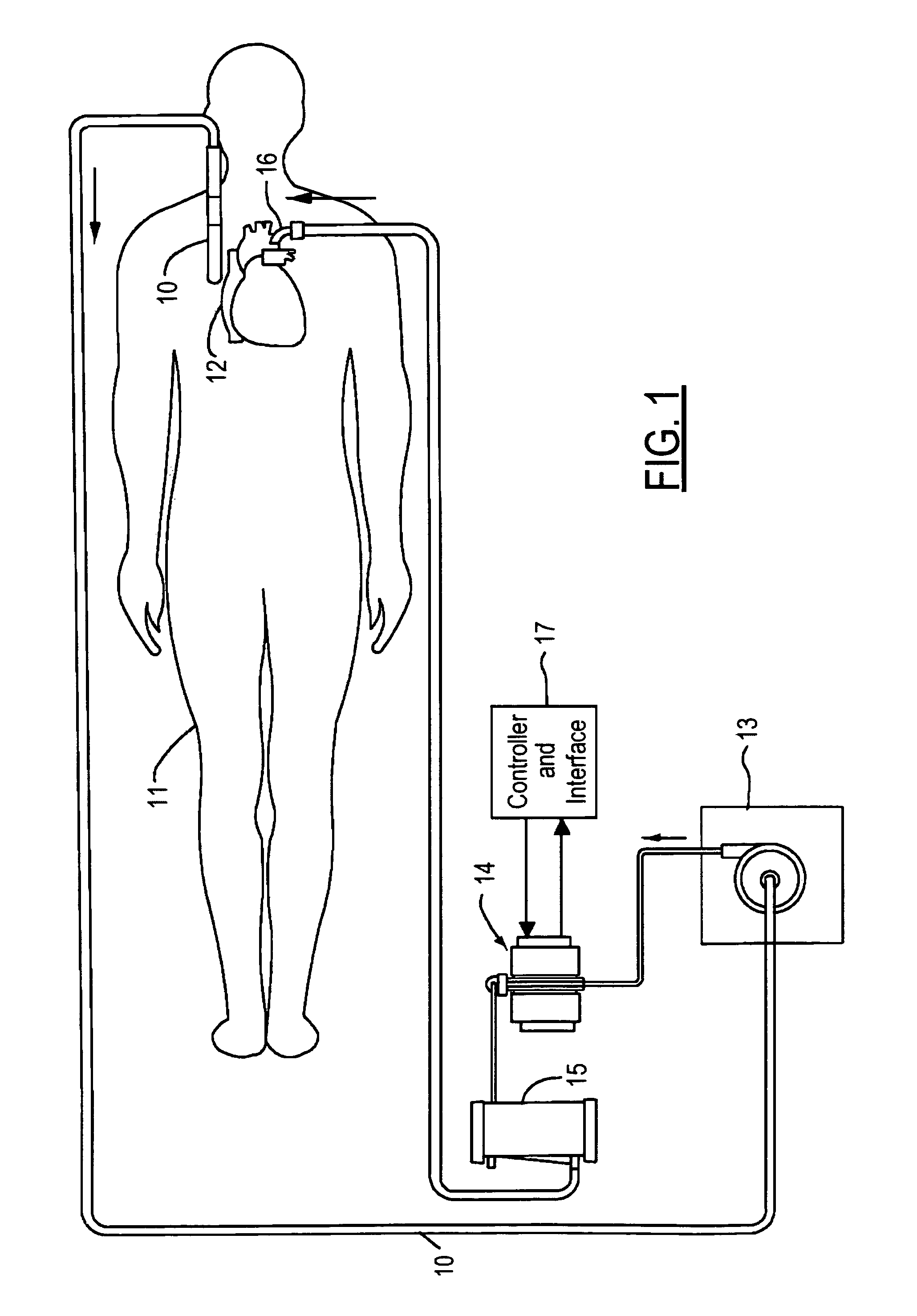
[0024]FIG. 1 shows a simplified diagram of a perfusion system for supporting on-pump coronary artery bypass graft surgery. A venous catheter 10 is inserted into a patient 11 to remove blood at a suitable point such as the superior or inferior vena cava 12. Venous blood is driven by an arterial pump 13 which may be comprised of a centrifugal or roller pump, for example. Blood passes through a heater / cooler device 14 and then to an oxygenator 15. Oxygenated blood is conducted to an arterial cannula 16 for return to the patient's aorta. A controller and interface 17 is connected to heater / cooler 14 to allow a medical technician to selectably control the temperature of blood flowing in the perfusion circuit and / or the temperature of a cardioplegia solution.

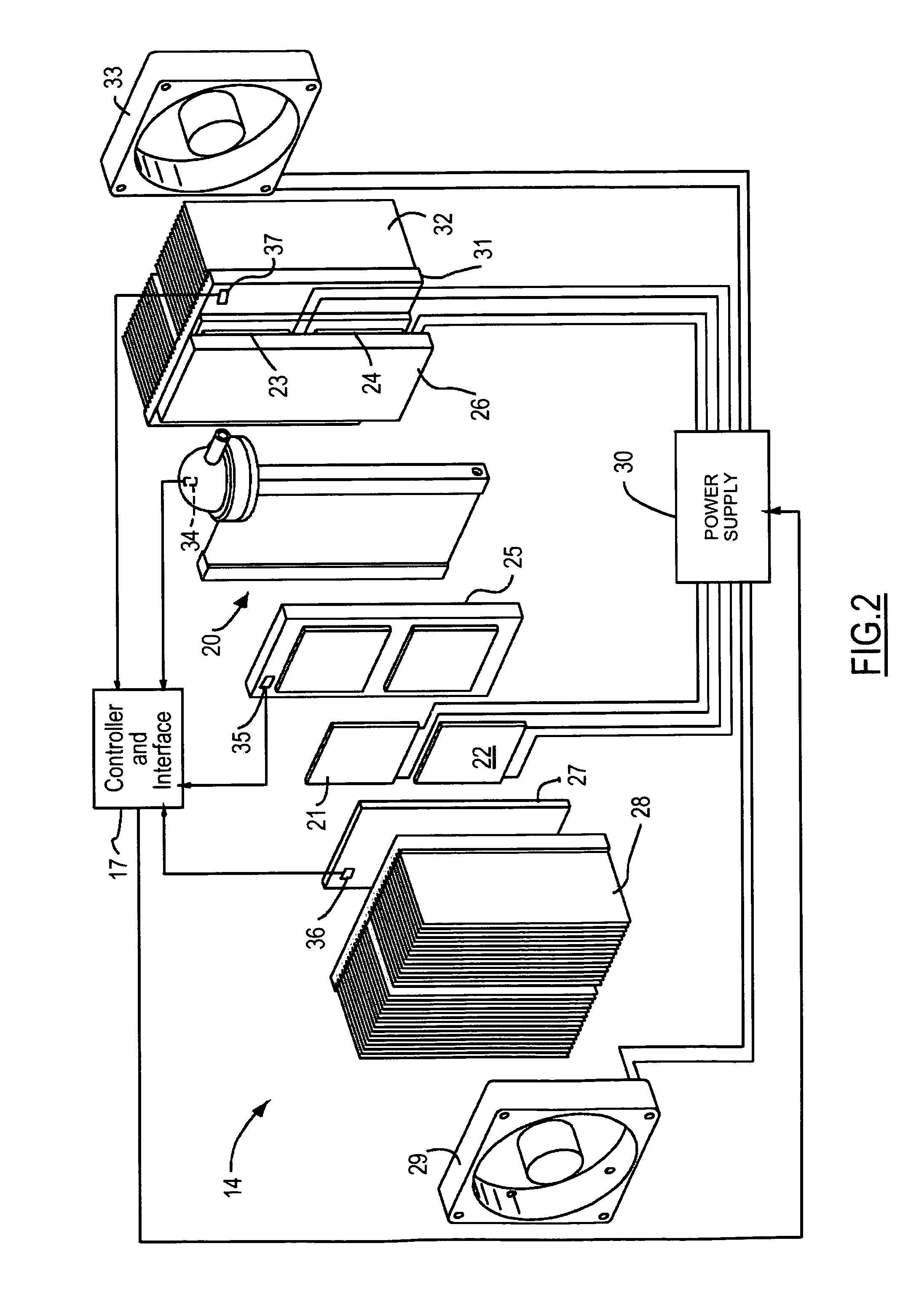
[0025]The heater / cooler device of the present invention utilizes thermoelectric modules as the source of heating and cooling. Thermoelectric devices comprise two ceramic substrates disposed on opposite sides of semiconductor materials...


PUM


Abstract

A waterless blood heater / cooler device directly controlling temperature of blood flowing through an extracorporeal blood circuit. A thermoelectric module is coupled to a supply voltage to generate a temperature difference. A heat exchanger cassette comprising a core and first and second laminar flow guides is in thermal contact (directly or indirectly) with the thermoelectric module. The cassette has a plurality of tubes for carrying parallel channels of the blood. The first and second laminar flow guides provide an inlet and an outlet for coupling to the extracorporeal blood circuit and respective intermediate chambers for receiving respective ends of the tubes in order to guide the blood to and from respective tubes in a substantially laminar flow.

Description

CROSS REFERENCE TO RELATED APPLICATIONS[0001]Not Applicable.STATEMENT REGARDING FEDERALLY SPONSORED RESEARCH[0002]Not Applicable.BACKGROUND OF THE INVENTION[0003]The present invention relates in general to blood perfusion systems for cardiac surgery, and, more specifically, to a waterless blood heater / cooler.[0004]Heating and cooling devices are an important part of blood perfusion systems used during cardiac surgery. During surgery, blood is cooled in a bypass circuit to induce hypothermia to protect the organs. A separate cardioplegia circuit typically provides a dedicated flow of cooled solution directly to the heart, at least periodically. When the surgery has been completed, the blood and / or other fluids flowing in the two circuits are heated prior to the patient waking from anesthesia. During various circumstances that may arise during operation of the blood perfusion system, it becomes desirable not only to heat both circuits or cool both circuits simultaneously, but also to ...

Claims


Application Information

Patent Timeline
Patent Type & Authority Patents(United States)
IPC IPC(8): A61M37/00B01J19/00F28F3/12F28F1/00F28F7/00A61C5/06F25F21/02
CPCA61M1/3666A61M2205/127A61M2205/3606A61M2205/3653A61M2205/3673A61M2206/11A61M1/3667A61M1/36223A61M1/36224A61M1/3623
Inventor ECCLESTON, ROLANDO A.
Owner TERUMO CARDIOVASCULAR SYST CORP
Why Eureka
Try Eureka