P-static energy source for an aircraft

a technology of p-static energy source and aircraft, which is applied in the direction of generator/motor, machine/engine, emergency protective arrangement for limiting excess voltage/current, etc., and can solve the problem of not making measurements presently

Inactive Publication Date: 2009-09-22
JARVINEN PHILIP ONNI
View PDF5 Cites 34 Cited by
  • Summary
  • Abstract
  • Description
  • Claims
  • Application Information

AI Technical Summary

Benefits of technology

[0032]It is a further objective of the present invention that the means to dump excess electric charge overboard into the passing airflow be local and be automatic so as to prevent voltage build-up which would exceed the voltage capabilities of the capacitor (or battery) storage unit and power conditioning elements. For example, dumping of excess charge to be accomplished through a metallic charge discharge unit consisting of a pad covered with a multitude of slender, conducting, sharp metallic bristles which extend out into the airflow.
[0033]It is a further objective of the present invention that overvoltage protection circuits be included to protect the P-Static Electrical Power System from any unwanted high voltage spike that might try to enter from the upst

Problems solved by technology

These measurements are not made presently because of the complexity and cost of doing so.
Such a condition may occur when the rechargeable capacitors (or rechargeable batteries) are fully charged and the device being powered is not con

Method used


Image

  • P-static energy source for an aircraft
  • P-static energy source for an aircraft
  • P-static energy source for an aircraft

Examples


Embodiment Construction

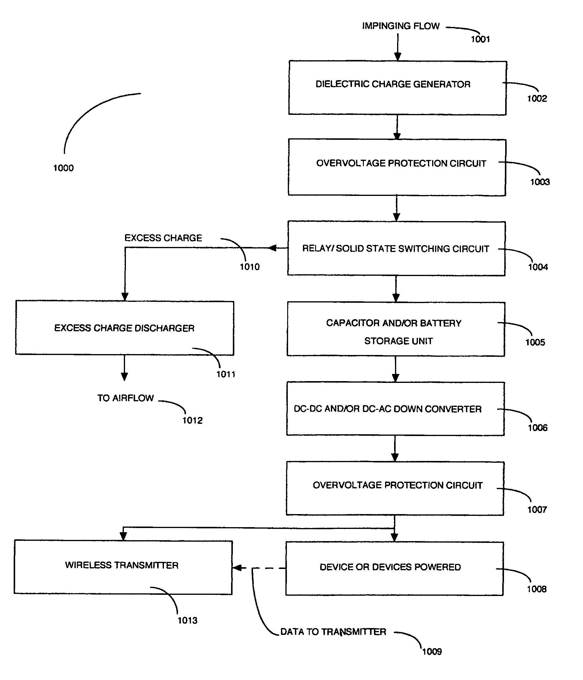
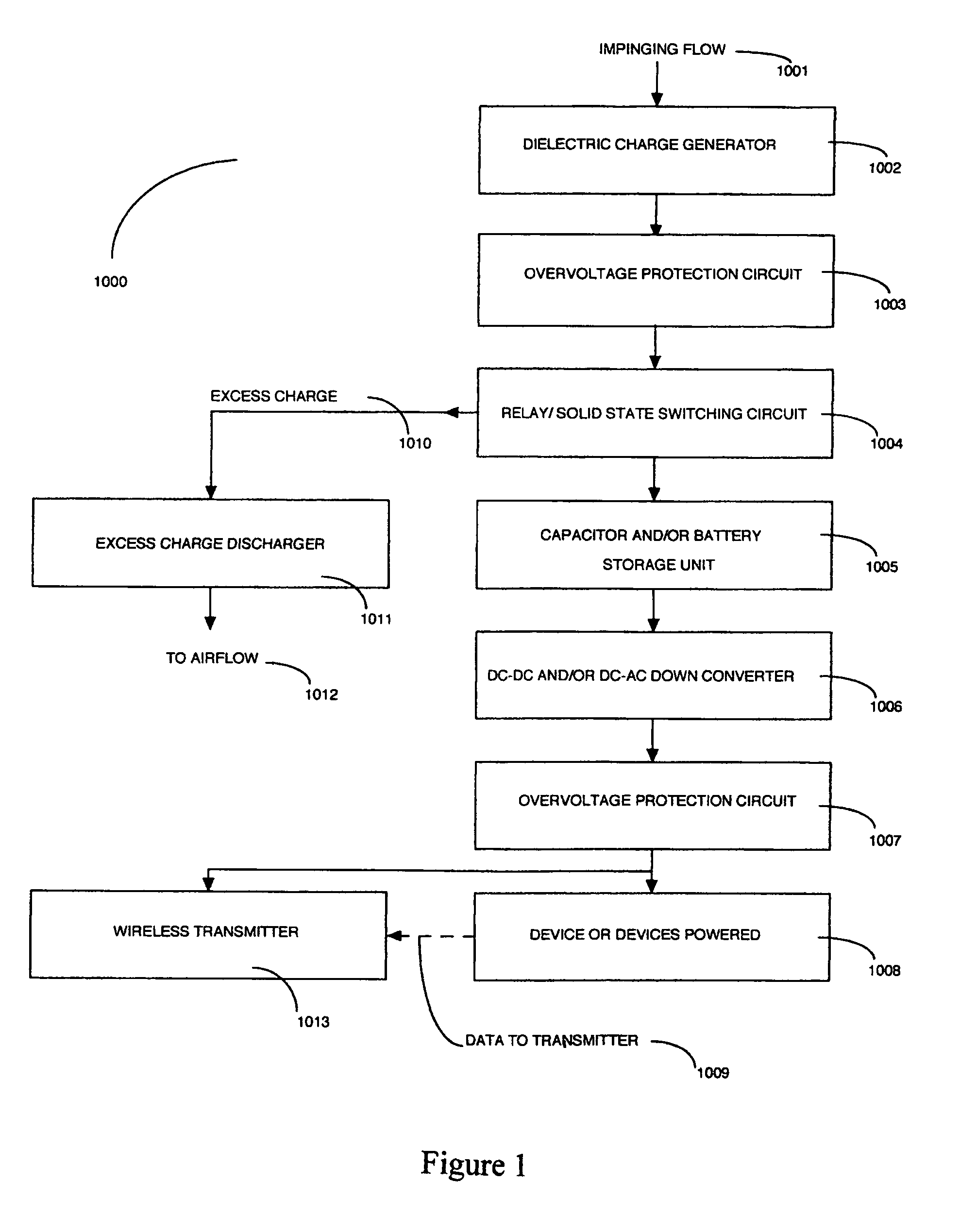
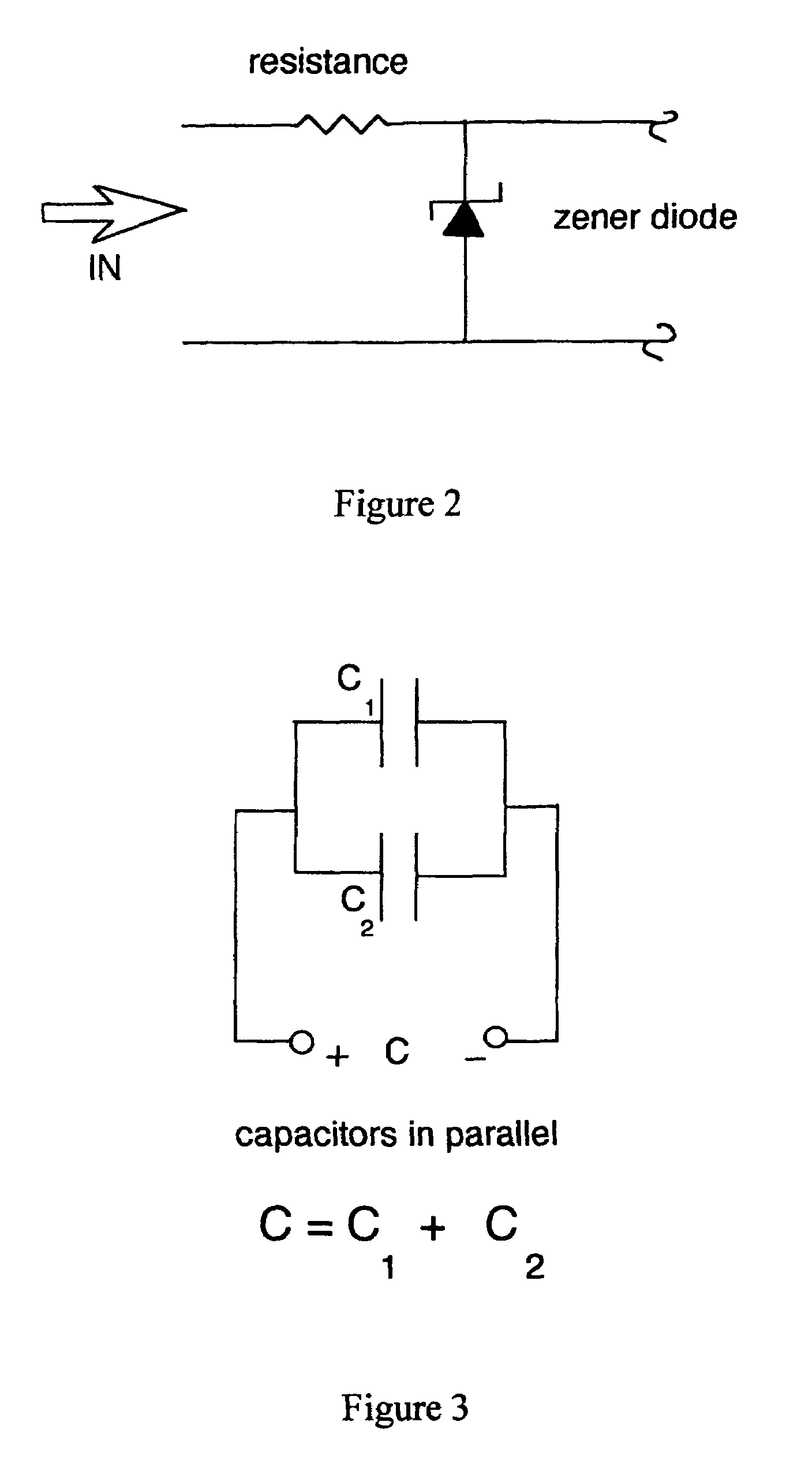
[0045]Referring now to the drawings and in particular to FIG. 1, the present invention discloses the block diagram 1000 which includes impinging flow with charging ingredients 1001, a dielectric charge generator 1002, an upstream overvoltage protection circuit 1003, a relay / solid state switching circuit 1004, a rechargeable capacitor (or rechargeable battery) energy storage unit 1005, a DC-to-DC and / or DC-to-AC step down converter 1006, a downstream overvoltage protection circuit 1007, a device or devices to be powered 1008, information and data to wireless transmitter 1009, excess charge 1010, an excess charge discharger 1011, airflow 1012, a wireless transmitter 1013 and an adjacent lightning protection unit (not shown). The upstream overvoltage protection circuit 1003 consists of a zener diode and resistance (or equivalent circuit) placed in the main circuit as shown in FIG. 2. The downstream overvoltage protection circuit 1007 also consists of a zener diode and resistance (or eq...


PUM


Abstract

A means for harvesting local energy and using it to generate local electric power is disclosed which uses as its energy source P-Static charge generated on the external surfaces of aircraft flying through the earths atmosphere or generated on the external surfaces of electrically ungrounded objects immersed in the wind and subjected to the impact of charge generating ingredients contained in the atmosphere or wind. The P-Static charge is collected and stored in a high voltage rechargeable capacitor storage unit at several thousand volts with energy removed from the storage unit as needed and converted to low voltage DC or AC power which, in turn, is used to power local, low power consumption electronic chips and devices. Data measured by the chips or devices is relayed wirelessly back to a receiver located within the aircraft or object with the wireless transmitter also powered by the P-Static Electrical Power System.

Description

COPYRIGHT NOTICE[0001]A portion of the disclosure of this patent document contains material that is subject to copyright protection. The copyright owner has no objection to facsimile reproduction of the patent document or the patent disclosure, as it appears in the Patent and Trademark Office patent file or records, but otherwise reserves all copyright rights whatsoever.FIELD OF THE INVENTION[0002]The invention relates to the field of energy harvesting. In particular, it relates to the harvesting of P-Static electrical charge generated on external surfaces of an aircraft flying through the earths atmosphere or on the external surfaces of any electrically ungrounded object subjected to the wind and the use of the P-Static charge, harvested and conditioned locally, to power local low power consumption, low operating voltage electronic chips and devices and, in addition, to power a wireless transmitter that relays locally measured information and / or data back to a central receiver for ...

Claims


Application Information

Patent Timeline
IPC IPC(8): H02N1/00
CPCH02N1/04
Inventor JARVINEN, PHILIP ONNI
Owner JARVINEN PHILIP ONNI
Why Eureka
Try Eureka