Process for the treatment of saline water

a technology for impaired water and saline water, applied in water/sewage treatment by ion exchange, alkali metal halide purification, magnesium compounds, etc., can solve the problems of increasing membrane replacement costs, preventing the discharge of waste water, and shortening the life of membranes, so as to reduce the volume and salt load of ro concentrate, reduce thermal equipment size, and reduce the effect of zld costs

Inactive Publication Date: 2009-09-29
GEO PROCESSORS
View PDF24 Cites 70 Cited by
  • Summary
  • Abstract
  • Description
  • Claims
  • Application Information

AI Technical Summary

Problems solved by technology

These regulations often even prohibit the discharge of any waste water.
Pre-treatment of feed to RO desalination plants is known to constitute a significant portion of the total operating costs of RO desalination processes (K. S. Speigler and Y. M. El-Sayed, 1994; Sandia and Bureau of Reclamation, 2003).
If left untreated, the elevated concentration of certain dissolved solids (such as silica, sulphate, bicarbonate and certain metals) may be a cause of damage to RO membranes resulting in shorter membrane life and increased membrane replacement costs.
Current ZLD processes involving the evaporation of effluent by thermo-mechanical means to a solid residue (or salt cake) for land fill disposal are very expensive both in terms of capital and operating costs.
In addition, they require land filling which contributes to environmental concerns.
Additionally, the large energy consumption of brine concentrators represents a major disadvantage.
While this process may improve salt quality, it is limited in application to seawater type saline waters that are first concentrated several fold.
A further drawback of this process is the use of calcium chloride as the sole reagent for the removal of sulfate, thus limiting the usefulness of this process to certain saline impaired water types.
A related major disadvantage of this process is its high capital and reagent costs.
Major disadvantages of this process are that it considers only waters with a TDS of over 30 g / L and fails to recover bicarbonate ions in the form of a useful product.
Furthermore, the process uses relatively costly reagents and it is acknowledged by the inventor to produce a waste stream, although minimal, and is thus precluded from consideration as a ZLD process.
However, these processes commonly require direct reaction of calcium oxide with carbon dioxide gas, the generation of which gas is costly and usually requires a large and expensive energy input, thus adding significantly to the cost of the PCC production.
Also, the aforementioned processes suffer from the disadvantage of the need for accurate control of process conditions so to ensure that the physical properties of the PCC product are as desired and, particularly, to achieve the desired particle size and morphology.
The two stage reaction described in the latter patent leads to significant loss of magnesium ions during the desulphation stage.
This method for the production of magnesium hydroxide also generates a significant volume of partially processed water which requires disposal.
Consequently, it is considered unsuitable for comprehensive treatment of saline impaired waters to meet the goals of ZLD.
Whereas the prior art processes described above generally claim to be conducive to the reduction of the salt load of the saline waste water and the alleviation of some of the problems associated with effluent disposal, none of these processes can be regarded as a ZLD process because partially processed water, waste effluent and / or slurry emanate from them, which require disposal.
The aforementioned processes for the production of magnesium hydroxide also require pretreatment by either evaporation or cooling and are limited in their use of alternative reagents for cost effective recovery of products.
Where these processes are used for the treatment of concentrate generated by known desalination processes, the broader application of these processes is limited primarily due to the inability to achieve ZLD objectives.

Method used


Image

  • Process for the treatment of saline water
  • Process for the treatment of saline water
  • Process for the treatment of saline water

Examples


example 1

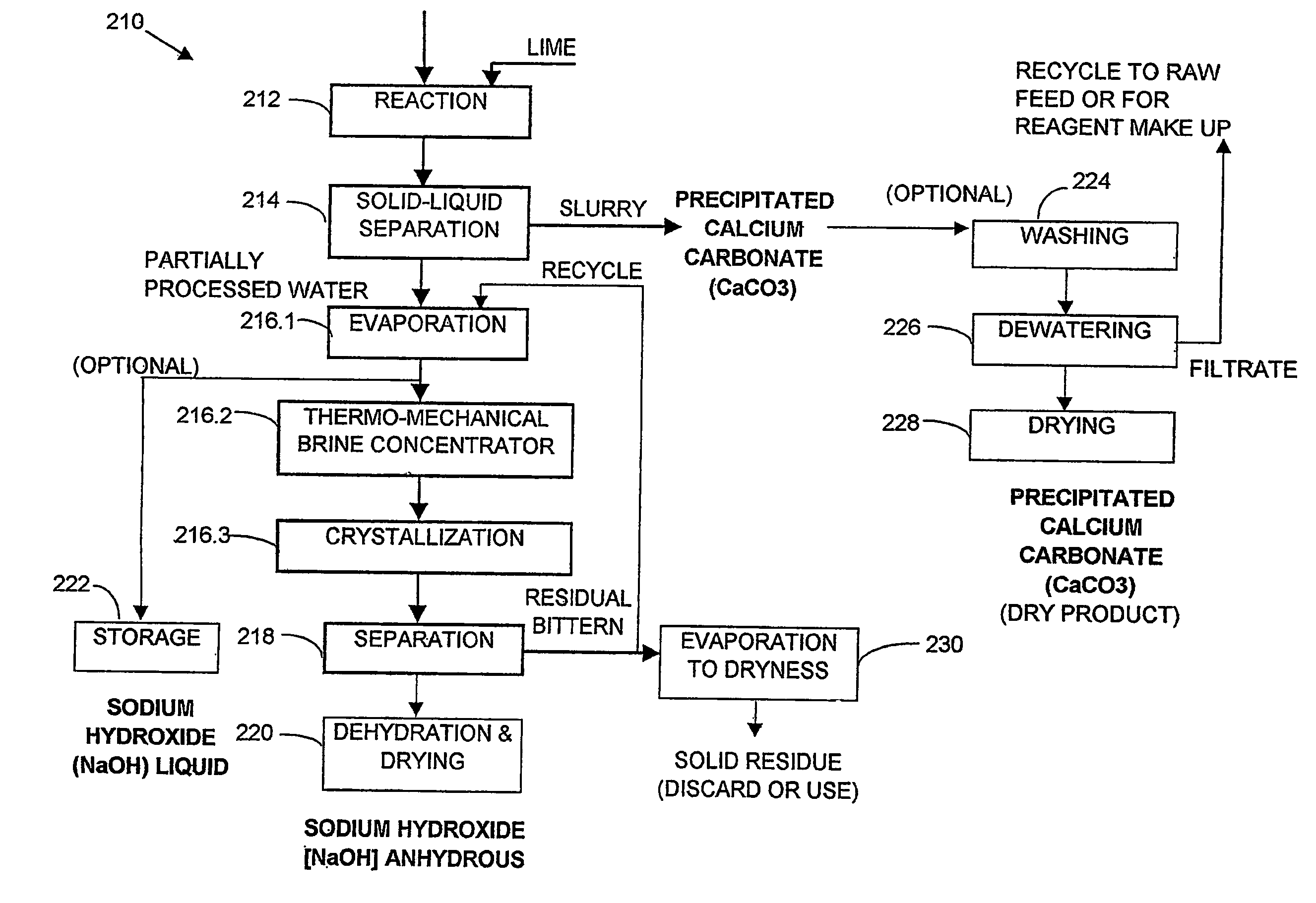
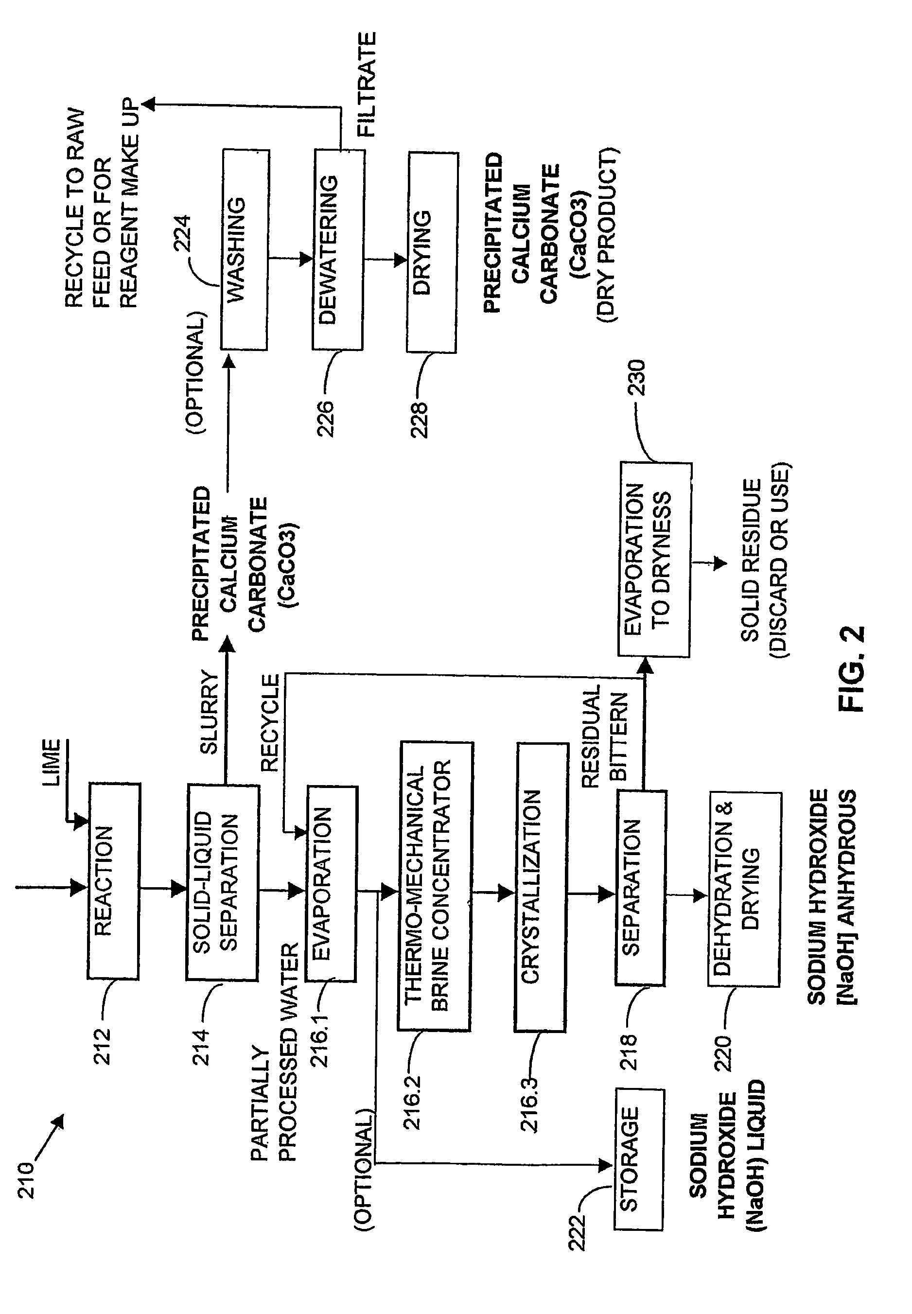
[0356]One thousand liters of saline impaired water from a ground water source, which analysed as having 3700 mg / L sodium, 74 mg / L potassium, 120 mg / L magnesium, 49 mg / L calcium, 8540 mg / L bicarbonate, 144 mg / L sulphate, 550 mg / L chloride and determined as having 13.2 g / L TDS, was reacted with a hydrated lime slurry under strong agitation for 60 minutes according to reaction [1]. The lime slurry used contained 10 wt % solids. After reaction, the slurry so produced was separated and thickened in a thickener. The thickened slurry from the under flow was then washed in a 3 stage counter current washing unit at a volume ratio of 5 parts of washing water to 1 part of thickened slurry. The washed slurry was dried giving 13.2 kg of precipitated calcium carbonate (PCC) comprising 98.7 wt % CaCO3, 0.5 wt % Mg(OH)2, 0.3 wt % NaCl and 0.5 wt % moisture content, and having a particle size within the range of 0.5-1.0 micron.

[0357]The partially processed water (over flow of the main thickener), wa...

example 2

[0359]One thousand liters of the water used in Example 1 was split into two streams of five hundred liters each. The first stream was reacted with hydrated lime slurry according to reaction [1], with the lime slurry containing 10 wt % solids, at a dosage sufficient to convert 100% of the stoichiometric amount of HCO3− to precipitated calcium carbonate (PCC), under strong agitation for 60 minutes, at a pH of about 11.8.

[0360]After reaction, the product slurry was separated and thickened in a thickener. The thickened slurry from the underflow was washed in a three stage, counter current, washing circuit at a ratio of 5 parts of washing water to 1 part of thickened slurry. The washed slurry, after drying, yielded 6.5 kg of precipitated calcium carbonate (PCC) of the same quality as the PCC in Example 1 (representing 95% of the stoichiometric amount of HCO3− recovered as PCC). The partially processed water (overflow of the main thickener) was added to the second 500 L portion of the fee...

example 3

[0361]One thousand liters of saline impaired water from a surface mining operation which analysed as containing 1420 mg / L sodium, 11 mg / L potassium, 18 mg / L magnesium, 17.8 mg / L calcium, 1600 mg / L bicarbonate, 886 mg / L sulphate, 1060 mg / L chloride and determined as having 5 g / L TDS was first filtered through a sand filter and then desalinated using a reverse osmosis unit, giving 50% by volume permeate recovery (500 liters of fresh water) with a salinity of 30 mg / L TDS. 500 liters of concentrate with a salinity of 9.4 g / L TDS was produced. This concentrate was reacted with a hydrated lime slurry having a solids content of 10 wt %, for 60 minutes, under strong agitation, according to reaction [1]. The slurry from the reaction was then separated and thickened in a thickener and the thickened slurry from the underflow was washed in a 3 stage washing unit at a ratio of 5 parts wash water to 1 part underflow slurry. The washed slurry was then dried to give 2.5 kg of PCC product. The PCC c...


PUM

PropertyMeasurementUnit
concentrationaaaaaaaaaa
temperatureaaaaaaaaaa

Abstract

A process and an apparatus are described for treating seven types of saline waters each having a concentration of total dissolved solids exceeding 1 g / L, wherein the concentration of total dissolved solids, the ratio of the chloride ion concentration to the bicarbonate ion concentration and the ratio of the chloride ion concentration to the sulphate ion concentration of each of the water types are as indicated in Table 1. The process includes the steps of contacting the water with a first reagent comprising a source of calcium ions selected from calcium oxide and calcium hydroxide to form a first solid product which is recovered. The process includes a further step of subjecting at least a portion of the partially processed water to at least partial evaporation so as to promote the formation of a precipitate and a mother liquor. The precipitate is recovered as a second product.

Description

FIELD OF THE INVENTION[0001]This invention relates to the treatment of saline impaired water. More particularly, the invention relates to a process and apparatus for the comprehensive treatment of saline impaired water, for the recovery of useful products therefrom and / or for the avoidance or elimination of liquid effluent.BACKGROUND OF THE INVENTION[0002]Saline impaired waters originate from many sources and exhibit diverse salinity levels and chemical compositions, largely reflecting the source, the extent of natural erosion processes and contaminant input by human activities.[0003]Large occurrences of saline impaired water, characterised by elevated alkalinity and salinity and emanating from ground water sources are recorded from many sedimentary basins in Australia and elsewhere. Such saline impaired waters are particularly common in those sedimentary basins incorporating coal beds and seams at sub-surface depths.[0004]Saline impaired water is sometimes evaporated in evaporation...

Claims


Application Information

Patent Timeline
Patent Type & Authority Patents(United States)
IPC IPC(8): C02F1/58B01D61/02B01D61/04C02F1/14C02F1/44C02F1/52C02F1/66
CPCB01D61/025B01D61/04C02F1/14C02F1/441C02F1/5245C02F1/66B01D2311/04C02F2103/10B01D2311/12Y02W10/37Y02A20/142Y02A20/131Y02A20/212Y02A20/124
Inventor ARAKEL, AHARONTIAN, HONGJUNSTAPLETON, LANCE JAMES
Owner GEO PROCESSORS
Why Eureka
Try Eureka