Methods and devices using a shrinkable support for porous monolithic materials

a monolithic material and shrinkable technology, applied in the field of components, can solve the problems of insufficient or poorly controlled contact between the porous material, diffusion broadening of chromatographic peaks, inadequate adsorption or catalysis, etc., and achieves reduced edge effects, superior results, and greater uniformity of flow

Active Publication Date: 2010-01-26
AGILENT TECH INC
View PDF29 Cites 58 Cited by
  • Summary
  • Abstract
  • Description
  • Claims
  • Application Information

AI Technical Summary

Benefits of technology

[0123]Some advantages and characteristics the present articles and methods include:
[0124]Glass or ceramic tubes processed by shrinking as described herein have smoother inner surfaces than equivalent metal or plastic tubes. The smoother inner surfaces produce superior results in applications such as chromatography, where the smoother surface produces reduced edge effects and greater uniformity of flow of mobile phase through the substrate bed (rather than between the substrate bed and the containing walls). As a result, chromatography columns produced by the methods described herein provide greater chromatographic efficiency, improved peak shapes, and reduced diffusion broadening.
[0125]In addition, the inventive devices and methods provide liquid tight contact between the porous inorganic substrate and the support. When utilized in the preparation of chromatographic columns, the method provides increased chromatographic efficiency and improved separation, peak shape, peak height, and the like. In addition, the devices and methods provide superior flow rates and decreased separation times. Similarly, the devices and methods can provide superior catalytic efficiencies by virtue of the superior flow properties of the devices.
[0126]High processing and operating temperatures can be tolerated and excellent solvent resistance can be provided.
[0127]Good support is provided for high-porosity monolithic media which can be fragile, such as the ultraporous sol-gel monolith described in co-pending US Patent Publication No. 2006 / 0131238.
[0128]The support is sufficient to allow for fabrication of outer plastic structures.
[0129]Shrinkage of the support to achieve target dimensions and to compensate for any shrinkage in the porous substrate is readily controlled. The method can be readily scaled to work for parts of widely-varying dimensions.
[0130]There is no longer a need to perform surface modifications to the internal surfaces of glass supports or to perform additional gelation steps in an attempt to cause the porous monolith to adhere to the glass support. As a result, the entire manufacturing process is simple, cost-effective and reproducible.
[0131]In the following examples, efforts have been made to ensure accuracy with respect to numbers used (e.g., amounts, temperature, etc.) but some experimental error and deviation should be accounted for. Unless indicated otherwise, temperature is in degrees ° C. and pressure is at or near atmospheric. All solvents were purchased as HPLC grade, and all reactions were routinely conducted in the air unless otherwise indicated.

Problems solved by technology

Leakage through gaps between the porous monolith and its supporting structure can result in insufficient or poorly controlled contact between the porous material and the fluid (or gas) and any components present therein, diffusion broadening of chromatographic peaks, inadequate adsorption or catalysis, etc.
However, many of these structures suffer from excessive leakage around the edges due to shrinkage of the porous monolith away from its associated support.
For this and other reasons, there is often significant shrinkage of the porous material during manufacture.
The use of a rigid support material may result in the appearance of excessive gaps at the inside wall after the completion of all manufacturing steps, and cause the porous material to be unsecured with respect to its supporting structure.
However, such polymer materials cannot be used in many applications, because the thermal and / or chemical resistance of the material is not compatible with the application.
However, such techniques are only suitable if the dimensions of the two parts to be assembled can be held to extremely tight tolerances, which may not be possible with porous monolithic materials.
Thus, although using glass as a shrinkable medium to provide sealing against metal parts is known in the art, it has not been used with porous monolithic materials to provide sealing between the containing or supporting walls and the porous monolith.
This problem has not been solved.
However, these references do not describe methods for providing a porous monolithic core having liquid tight contact between the porous monolith and the containing walls that is suitable for use in analytical or preparative devices, or the like.
In fact, the processes utilized in manufacture of optical fibers would be incompatible with retention of porosity in porous monolithic materials, as the presence of pores would reduce the optical clarity and transmittance of the fibers, and therefore, is an undesirable feature in optical fibers.
However, the fused silica capillaries have a very high melting temperature, and heating the capillary and porous monolith to a sufficiently high temperature to shrink the capillary down to maintain contact with the porous monolith as it forms and is further processed (e.g., dried and calcined) would destroy the porosity of the monolith, just as in the case of preparation of optical fibers.
However, PTFE does not provide sufficient support for fragile porous monoliths formed by sol gel methods, and cannot be heated to a temperature sufficient to calcine the sol gel monolith and remove organic contaminants.
The capillary can be further treated with heat up to 350° C. However, the above described techniques are only useful when working with small dimensions such as exist in capillary tubing, in which diameters are generally less than 1 mm and typically less than 0.1 mm.
For example, the largest diameter fused silica capillary tubing utilized by Malik was only 0.25 mm in diameter, and such small diameters limit the applications and utility of the method.
Another difficulty encountered in minimizing leakage or gaps between a porous monolith and its containing structure, especially when prepared using sol-gel methods, is that processing introduces shrinkage or cracking during the drying step of the fabrication process.
However, these additional processing steps are time consuming and the products are expensive to manufacture.
However, these processes for producing a porous monolith with reduced shrinkage sacrifice control of the gel composition, porosity and pore size distribution, and the porous monolithic materials produced lack in mechanical strength.

Method used


Image

  • Methods and devices using a shrinkable support for porous monolithic materials
  • Methods and devices using a shrinkable support for porous monolithic materials
  • Methods and devices using a shrinkable support for porous monolithic materials

Examples


example 1

Preparation of a Porous Monolith and a Support in Liquid Tight Contact

[0132]The nonionic surfactant Pluronic F68 (0.44 g, BASF) was dissolved in a mixture of 1.1 g water, 3.6 g methanol, 2.1 g reagent alcohol and 0.96 g HF (2.6 M). While stirring, 5.0 ml tetraethoxysilane (TEOS) was introduced into the above solution and formed a uniform mixture. After 5 minutes, the sol was injected into a polymer tubing of 1.6 mm inner diameter (ID). Thirty minutes later, the sol became white gels, which were then aged, dried and transferred to a furnace for calcination at a temperature of about 550° C. overnight. Gels were removed from the tubing prior to calcination.

[0133]The final outside-diameter of the porous monolith was about 1.2 mm. BET surface area, mesopore volume and mode diameter measurements were performed using a Micromeritics TriStar 3000: the BET surface area was about 400 m2 / g, the mesopore volume was 1.1 cm3 / g, and the mesopore diameter was about 100 Å. The total pore volume was ...

example 2

Preparation of a Porous Monolith and a Support in Liquid Tight Contact

[0137]A mixture was prepared according to Example 1: the nonionic surfactant Pluronic F68 (0.44 g, BASF) was dissolved in a mixture of 1.1 g water, 3.6 g methanol, 2.1 g reagent alcohol and 0.96 g HF (2.6 M). While stirring, 5.0 ml TEOS was introduced into the above solution and formed a uniform mixture.

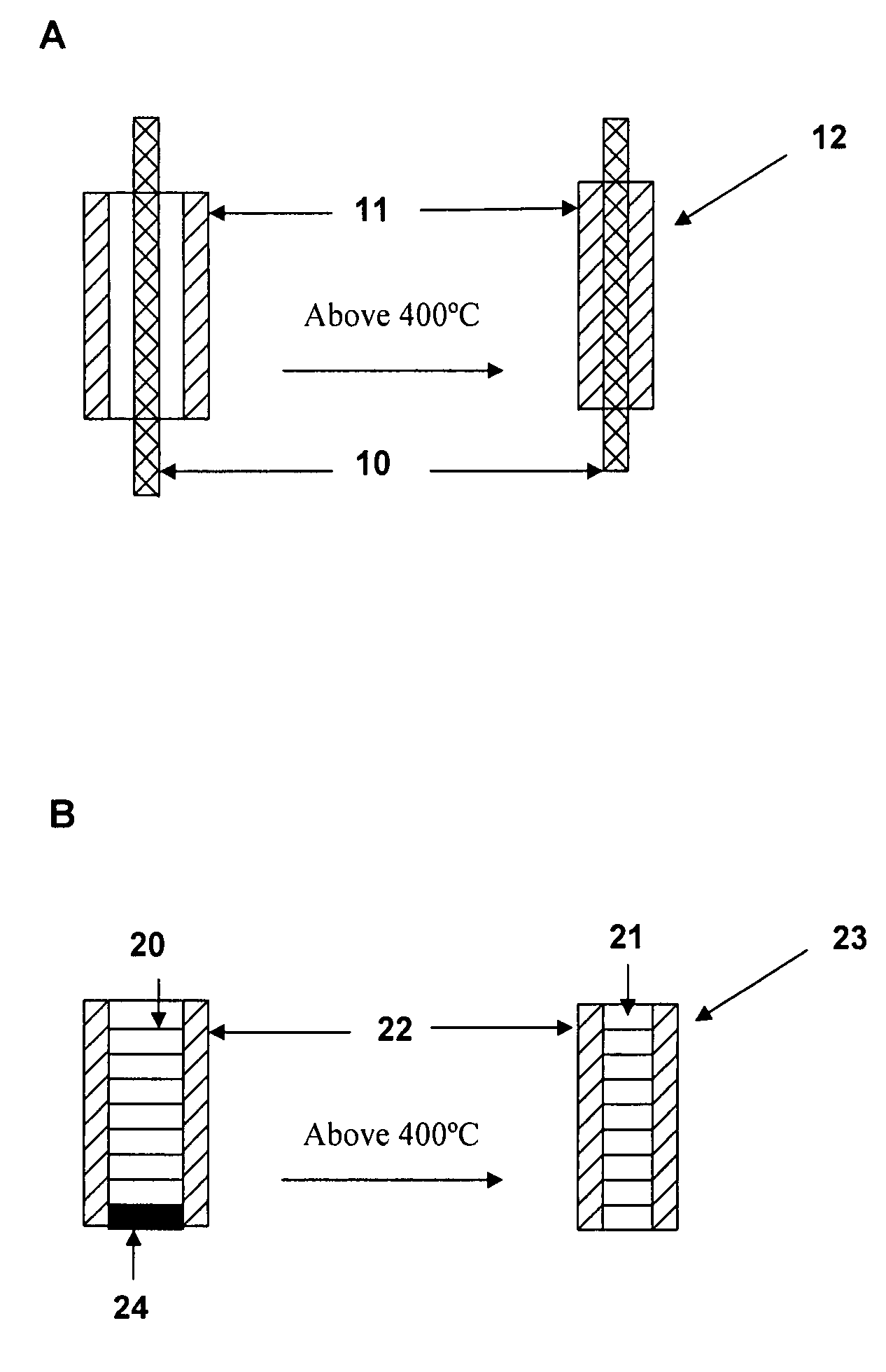
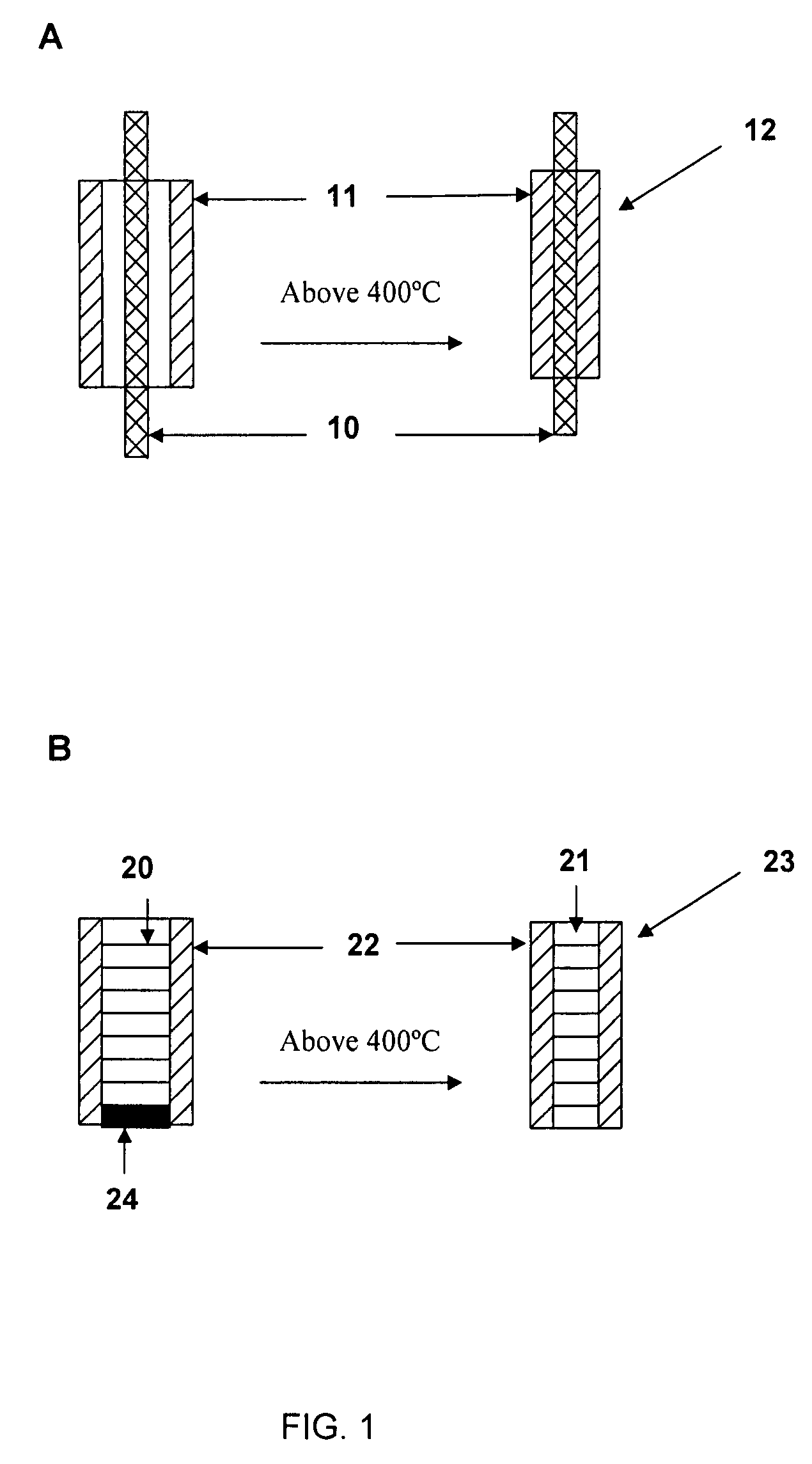
[0138]After 5 minutes, the sol was injected into a 2.4 mm ID glass tubing. Thirty minutes later, the sol became white gels, which were then aged, dried and calcined at a temperature of about 550° C. The silica monolith inside the glass tubing had shrunk from 2.4 mm to about 2.0 mm, and was now loose within the glass tubing.

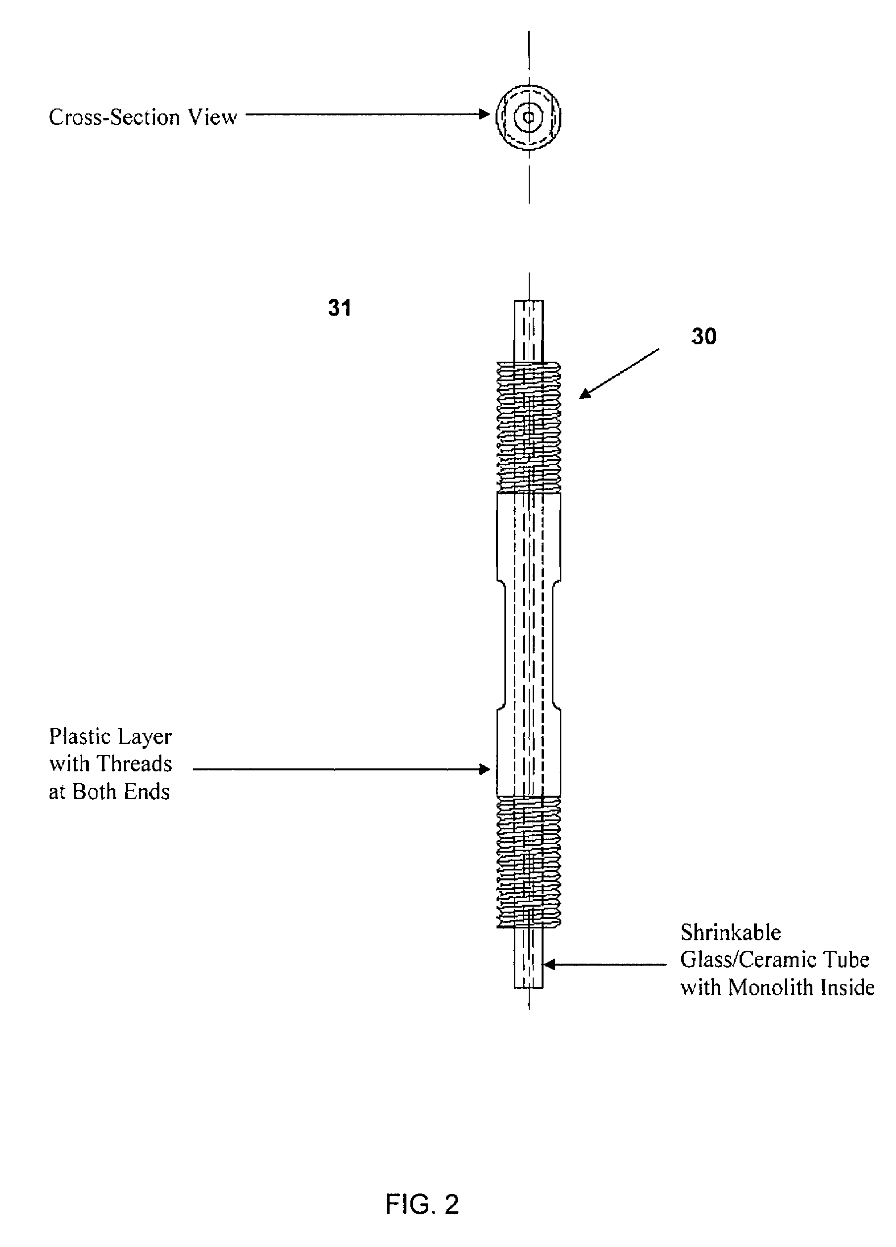
[0139]The gel and glass tubing were then subjected to heat treatment at a temperature of 850° C. After the gel cylindrical surfaces were completely sealed, the glass column was cut into 100 mm long pieces, which were over-molded using liquid crystal polymer as described in Example 1, with both en...

example 3

Preparation of a Porous Monolith and a Support in Liquid Tight Contact

[0140]The protocol according to the Example 1 was repeated, with the following difference: one end of the borosilicate glass tubing with the porous monolith inside was sealed by melting the glass at the end of the tubing only. When the glass cooled, a vacuum (about 20 inches of mercury) was applied to the open end of the tubing, and the glass tubing with the porous monolith inside was heated to a temperature at which the glass tubing softened and shrunk under the force of the outside atmospheric pressure to form a tight seal with the silica monolith inside. Use of a vacuum allowed the shrinkage to occur at a lower temperature than in the absence of the vacuum, allowing a broader range of temperatures suitable for the shrinkage step.


PUM

PropertyMeasurementUnit
diametersaaaaaaaaaa
diametersaaaaaaaaaa
diametersaaaaaaaaaa

Abstract

Articles of manufacture and devices and methods of forming and using the same are provided, wherein the article comprises a porous inorganic substrate contained in or bounded by a support made from an inorganic material are provided, wherein said porous substrate and support are heated to a temperature effective to shrink the support onto the porous substrate such that liquid tight contact is formed between the porous substrate and the support. In a preferred aspect, the porous inorganic substrate has a porosity of at least 5%, and is a porous monolith formed using a sol-gel method. The articles thus formed provide a confined fluid flow through the porous substrate, providing superior performance in separations, catalysis, filtration, and the like.

Description

FIELD OF THE INVENTION[0001]This invention relates generally to components useful in analytical or preparative applications and chemical processing or catalysis, and methods of preparing and using the same.BACKGROUND OF THE INVENTION[0002]Porous monolithic materials are used in a variety of applications such as filtration, adsorption and catalysis, among others. Such materials are often mounted in and contained in intimate contact with a supporting structure such as a containing tube, which both supports and protects the porous medium, and for some applications, confines the flow of a liquid or gas. For proper function of a particular process, it can be important to confine the fluid (or gas) flow through the porous monolith and to minimize flow around the porous monolith, which may occur when the fluid flows in gaps present between the porous monolith and its supporting structure. Leakage through gaps between the porous monolith and its supporting structure can result in insufficie...

Claims


Application Information

Patent Timeline
Patent Type & Authority Patents(United States)
IPC IPC(8): B32B3/26B01D15/08B29C35/00
CPCB01J20/28042B01J20/28054B01J20/282B01J35/04G01N30/6052B01J2220/82G01N30/56Y10T428/22G01N2030/528Y10T428/249953Y10T428/24997Y10T428/249987Y10T428/249967Y10T428/24999
Inventor XU, DENGFENGGRENZ, ROBERT LEE
Owner AGILENT TECH INC
Why Eureka
Try Eureka