Plasma spraying method

a technology of plasma spraying and spraying equipment, which is applied in the field of plasma spraying equipment, can solve the problems of high plant cost, inability to use the same tool for the lpps plasma spraying process and the eb pvd process in the manufacture of coatings including a plurality of partial coatings

Inactive Publication Date: 2010-03-16
SULZER METRO AG
View PDF17 Cites 23 Cited by
  • Summary
  • Abstract
  • Description
  • Claims
  • Application Information

AI Technical Summary

Benefits of technology

[0007]The method in accordance with the invention has a further advantage with respect to the known method with which a coating structu

Problems solved by technology

A disadvantage of this vapor deposition process is the high plant cost.
In addition, the same tool cannot be used for the LPPS

Method used


Image

  • Plasma spraying method
  • Plasma spraying method

Examples


Embodiment Construction

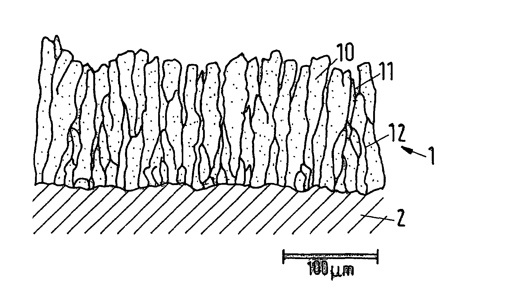
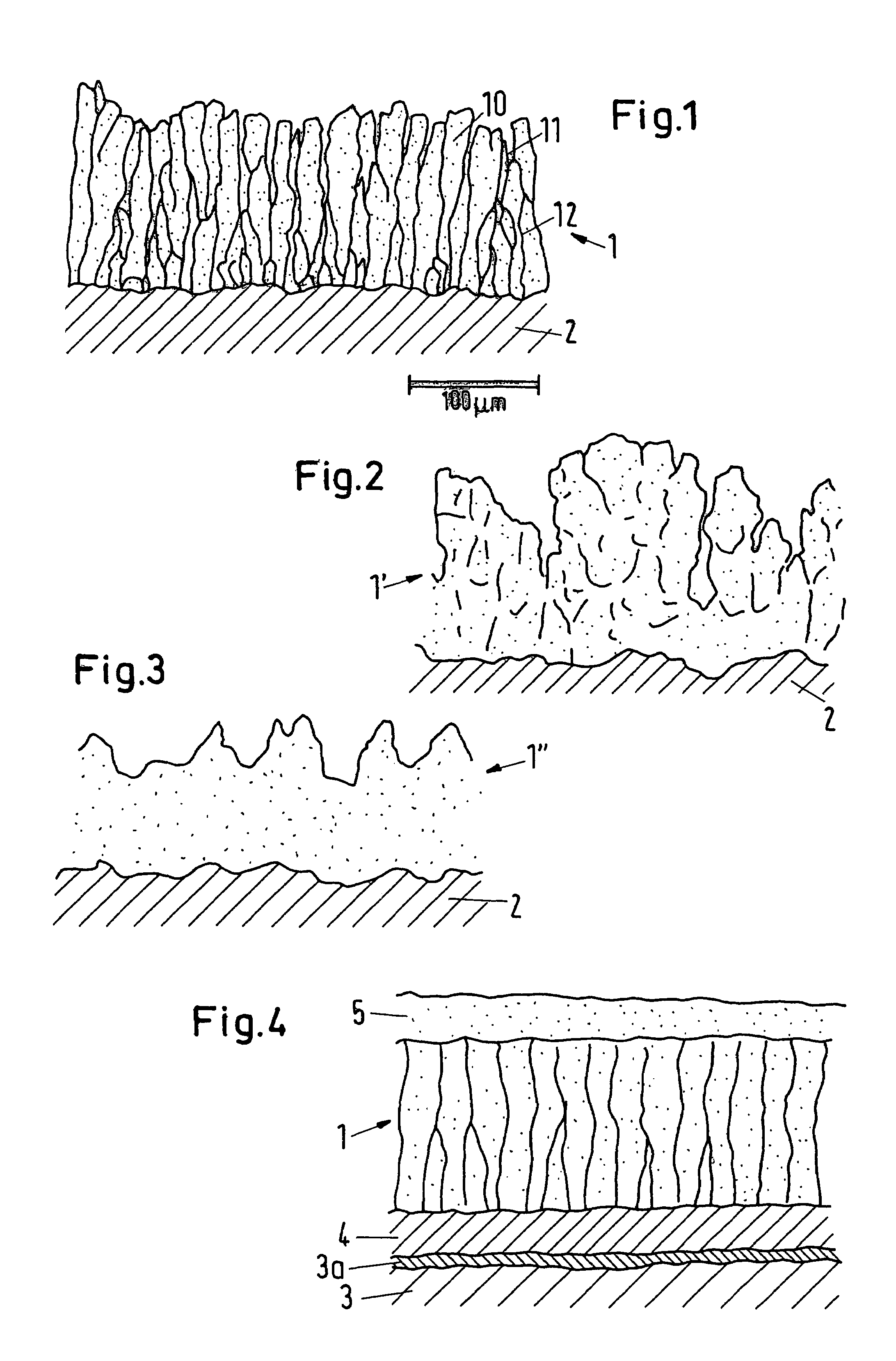
[0014]In FIG. 1, a section is shown through a coating 1 which was made using the method in accordance with the invention and which is drawn in accordance with a grinding pattern. The coating 1 deposited onto a substrate 2 with the LPPS thin film process has an anisotropic structure and a coating thickness of around 150 μm. The anisotropic micro-structure is formed by elongate particles 10 which stand largely perpendicular to the substrate surface. Low material transitional zones 12, which are drawn as lines, and gap-shaped intermediate spaces 11 bound the particles 10 from one another. Zirconium oxide stabilized with yttrium Y, namely

ZrO2-8% Y2O3, were used as the coating material. The substrate 2 is as a rule an adhesion promoting coating or a protection coating against corrosion.

[0015]So that the anisotropic micro-structure arises, a plasma must be produced with sufficiently high specific enthalpy so that a substantial portion—amounting to at least 5% by weight, of the coating mat...


PUM

PropertyMeasurementUnit
Size distributionaaaaaaaaaa
Lengthaaaaaaaaaa

Abstract

A method of forming a thermally insulating layer system on a metallic substrate surface is disclosed. The method includes: forming a plasma beam; introducing a coating material in the form of a powder having particles in the range between 1 and 50 μm, carried by a delivery gas into the plasma beam, so as to form a powder beam; defocusing the powder beam by using the plasma beam with a sufficiently high specific enthalpy and by maintaining a process pressure between 50 and 2000 Pa for at least partially melting and vaporizing at least 5% by weight of the powder, so as to form a vapor phase cloud; and forming from the vapor phase cloud onto the metallic substrate surface an insulating layer, being a part of the insulating layer system, having an anisotropic columnar microstructure having elongate particles; wherein the anisotropic columnar microstructure is aligned substantially perpendicular to the metallic substrate surface and low-density transition regions with little material delimit the elongate particles relative to one another.

Description

BACKGROUND OF THE INVENTION[0001]The invention relates to a plasma spraying method. The generic process, described in U.S. Pat. No. 5,853,815, is a thermal spraying for the manufacture of a so-called LPPS (=low pressure plasma spraying) thin film. The invention also relates to applications of the method and to components which are coated in accordance with the method in accordance with the invention.[0002]A conventional LPPS plasma spraying process is modified in the technical process by the LPPS thin film process, with a space through which plasma flows (“plasma flame” or “plasma beam”) being expanded due to the changes and extended to a length of up to 2.5 m. The geometrical extension of the plasma results in a uniform expansion—a “defocusing”—of a powder beam which is injected into the plasma with a delivery gas. The material of the powder beam, which disperses to form a cloud in the plasma and is partly or fully melted there, reaches a widely extended surface of a substrate in a...

Claims


Application Information

Patent Timeline
IPC IPC(8): C23C4/10C23C4/12H05H1/24H05H1/26
CPCC23C4/128C23C14/083C23C14/228C23C14/14Y10T428/265Y02T50/67C23C4/137Y02T50/60
Inventor BARBEZAT, GERARDREFKE, ARNOLOCH, MICHAEL
Owner SULZER METRO AG
Why Eureka
Try Eureka