Extreme ultra violet light source apparatus

a light source apparatus and ultra violet technology, applied in the field of extreme ultra violet (euv) light source apparatus, can solve the problems of sputtered mirror surface, high cost of euv collector mirror, and difficult to achieve the effect of improving the efficiency of microwave energy in ionization of neutral particles

Active Publication Date: 2010-04-27
GIGAPHOTON
View PDF4 Cites 22 Cited by
  • Summary
  • Abstract
  • Description
  • Claims
  • Application Information

AI Technical Summary

Benefits of technology

[0014]The present invention has been achieved in view of the above-mentioned problems. A purpose of the present invention is, in an extreme ultra violet light source apparatus that exhausts debris including fast ions and neutral particles by the effect of a magnetic field, to efficiently ionize neutral particles emitted from plasma.
[0016]According to the present invention, since the microwave for causing electron cyclotron resonance is radiated in pulse in synchronization with plasma generation, the utility efficiency of microwave energy in ionization of neutral particles can be improved.

Problems solved by technology

In the LPP EUV light source apparatus, the influence of fast ions and fast neutral particles emitted from plasma is problematic.
This is because the EUV collector mirror is located near the plasma and the reflecting surface of the mirror is sputtered and damaged by those particles.
Nevertheless, the EUV collector mirror is required to have the high surface flatness of about 0.2 nm (rms), for example, in order to maintain the high reflectance, and thus, the EUV collector mirror is very expensive.
However, JP-P2006-80255A does not disclose any characteristics and generation timing of microwave to be used for causing ECR.
This fact is problematic in view of effective use of energy.
Further, when thermal energy is emitted into the chamber, the generation of fine target jet or droplet target is disturbed and the state of the target becomes unstable.
Such instability of the target causes problems of reduction in output of generated EUV light, reduction in stability of EUV pulse energy, and so on, and further, leads to reduction in exposure performance in an EUV exposure equipment and reduction in exposure processing performance.
Further, another problem caused by continuous radiation of microwave is generation of X-ray.
The X-ray generation is a serious problem because X-ray has adverse effects on human bodies and environments.

Method used


Image

  • Extreme ultra violet light source apparatus
  • Extreme ultra violet light source apparatus
  • Extreme ultra violet light source apparatus

Examples


first embodiment

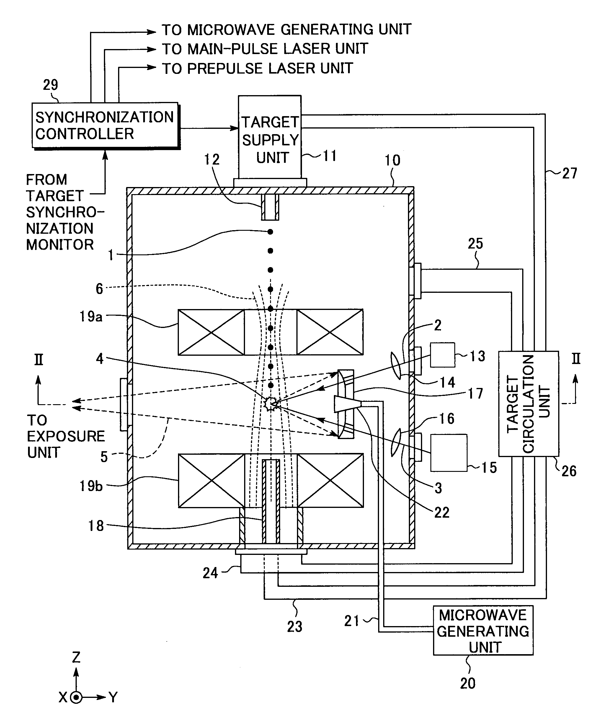
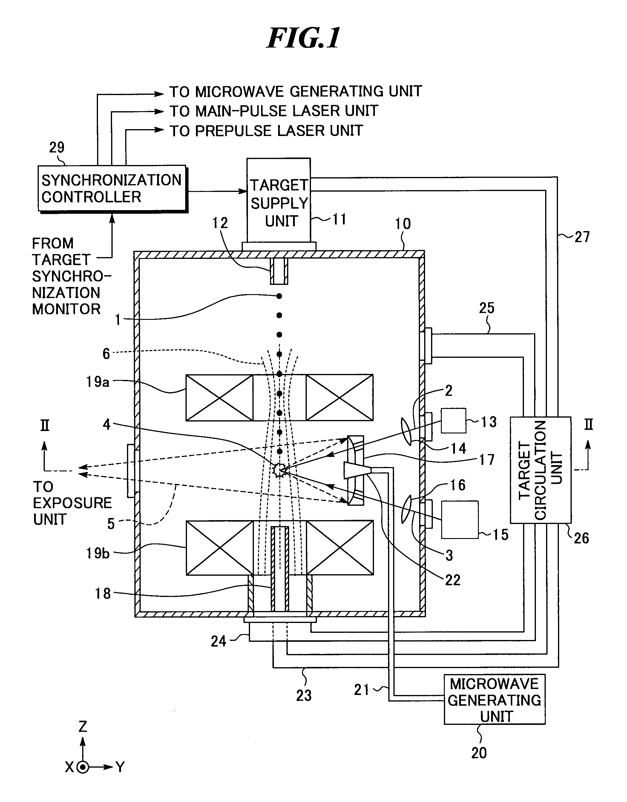
[0037]FIG. 1 shows a configuration of an extreme ultra violet (EUV) light source apparatus according to the present invention. Further, FIG. 2 is a sectional view along II-II shown in FIG. 1. The EUV light source apparatus according to the embodiment employs a laser produced plasma (LPP) system of generating EUV light by applying a laser beam to a target material to excite the target material.

[0038]As shown in FIGS. 1 and 2, the EUV light source apparatus includes a chamber 10 in which EUV light is generated, a target supply unit 11, a target nozzle 12, a prepulse laser unit 13, a main-pulse laser unit 15, collective lenses 14 and 16, an EUV collector mirror 17, and a target collection cylinder 18. The EUV light source apparatus according to the embodiment further includes electromagnets 19a and 19b, a microwave generating unit 20, a microwave waveguide 21, a microwave antenna 22, a target collection pipe 23, an ion exhaust tube 24, a target exhaust tube 25, a target circulation uni...

second embodiment

[0076]Next, an EUV light source apparatus according to the present invention will be explained with reference to FIG. 5. As shown in FIG. 5, the EUV light source apparatus according to the embodiment is further provided with an electron supply unit 31 and an electron supply controller 32 in addition to the EUV light source apparatus shown in FIG. 1.

[0077]The electron supply unit 31 is a unit for supplying electrons into the chamber 10. The position where the electron supply unit 31 is provided may be anywhere in the chamber 10 as long as electrons 7 emitted from the electron supply unit 31 may be allowed to reach a region where ECR is caused (i.e., near the plasma emission point). In the embodiment, the electron supply unit 31 is provided near the central opening of the electromagnet 19a. The electron 7 emitted to the position is guided to the vicinity of the plasma emission point along the lines of magnetic flux 6 by the effect of the magnetic field formed by the electromagnets 19a...

third embodiment

[0081]Next, an EUV light source apparatus according to the present invention will be explained with reference to FIG. 6.

[0082]As shown in FIG. 6, the EUV light source apparatus according to the embodiment is, in the EUV light source apparatus having the electron supply unit 31 and the electron supply controller 32, to control their operation by the synchronization controller 29. The rest of the configuration is the same as that shown in FIG. 5.

[0083]In the embodiment, the operation of the electron supply controller 32 is controlled to perform pulse operation based on the radiation start timing of microwave. Thereby, the timing at which the primary electrons 7 reach the application range of the microwave and the timing at which microwave radiation is started are made coincide with each other, and thus, the electron avalanche by ECR can be reliably caused with the appropriate timing. Further, since the minimum electrons 7 are introduced into the chamber 10, the reduction in degree of ...


PUM

PropertyMeasurementUnit
wavelengthaaaaaaaaaa

Abstract

In an extreme ultra violet light source apparatus that exhausts debris including fast ions and neutral particles by the effect of a magnetic field, neutral particles emitted from plasma are efficiently ionized. The extreme ultra violet light source apparatus includes a plasma generating unit that generates plasma, that radiates at least extreme ultra violet light, through pulse operation; collective optics that collects the extreme ultra violet light radiated from the plasma; a microwave generating unit that radiates microwave through pulse operation into a space in which a magnetic field is formed to cause electron cyclotron resonance, and thereby ionizes neutral particles emitted from the plasma; a magnetic field forming unit that forms the magnetic field and a magnetic field for trapping at least ionized particles; and a control unit that synchronously controls at least the plasma generating unit and the microwave generating unit.

Description

BACKGROUND OF THE INVENTION[0001]1. Field of the Invention[0002]The present invention relates to an extreme ultra violet (EUV) light source apparatus to be used as a light source in exposure equipment.[0003]2. Description of a Related Art[0004]In recent years, as semiconductor processes become finer, photolithography has been making rapid progress to finer fabrication. In the next generation, microfabrication of 100 nm to 70 nm, further, microfabrication of 50 nm or less will be required. Accordingly, in order to fulfill the requirement for microfabrication of 50 nm or less, for example, exposure equipment is expected to be developed by combining an EUV light source generating EUV light with a wavelength of about 13 nm and reduced projection reflective optics.[0005]There are three kinds of light used as an EUV light source: an LPP (laser produced plasma) light source using plasma generating by applying a laser beam to a target (hereinafter, also referred to as “LPP EUV light source ...

Claims


Application Information

Patent Timeline
Patent Type & Authority Patents(United States)
IPC IPC(8): A61N5/06G01J3/10H05G2/00
CPCG21K1/14H05G2/008H05G2/003
Inventor KOMORI, HIROSHIENDO, AKIRA
Owner GIGAPHOTON
Why Eureka
Try Eureka