Integrated semiconductor nonvolatile storage device

a semiconductor and non-volatile technology, applied in semiconductor devices, instruments, electrical devices, etc., can solve the problems of reducing the thickness its interface, affecting the charge retention characteristics, and affecting the stability of the insulating film

Active Publication Date: 2010-05-25
RENESAS ELECTRONICS CORP
View PDF6 Cites 22 Cited by
  • Summary
  • Abstract
  • Description
  • Claims
  • Application Information

AI Technical Summary

Benefits of technology

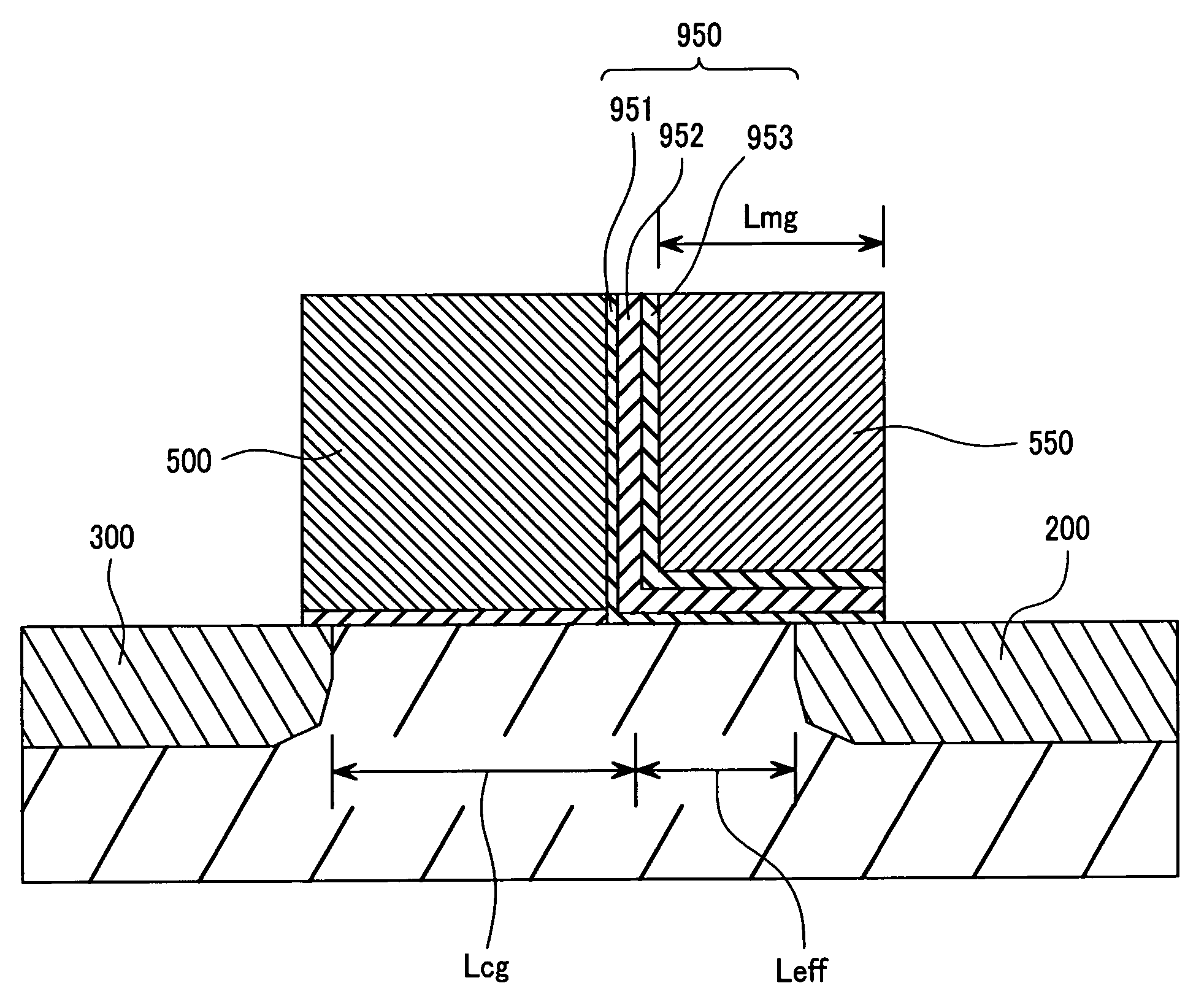
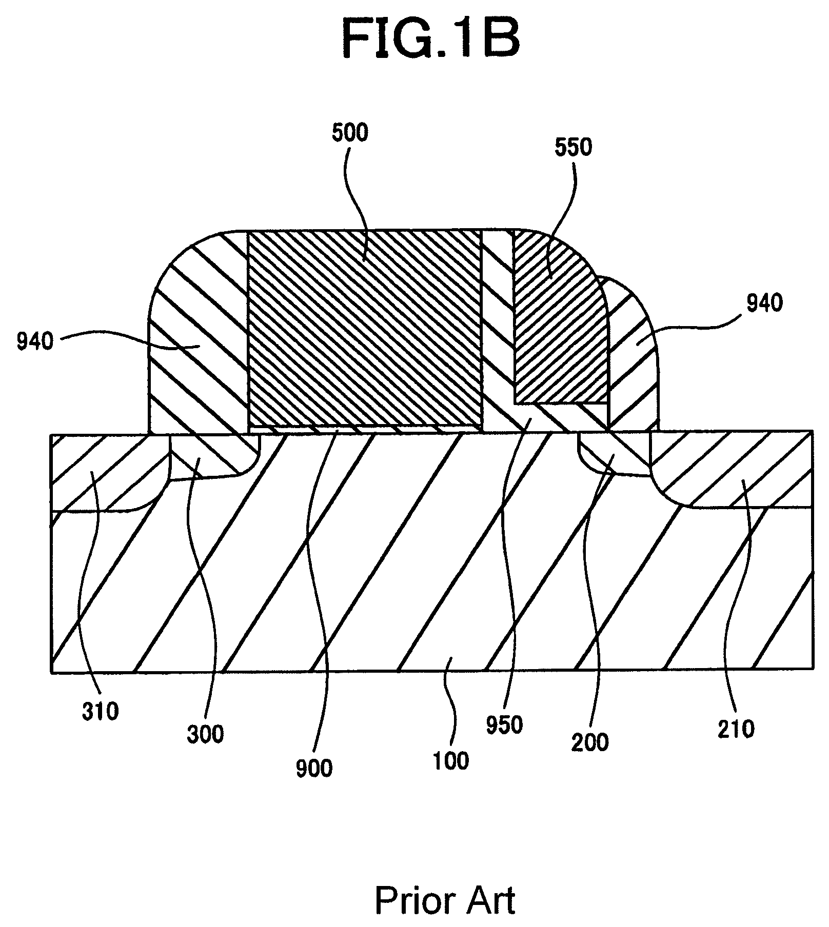
[0023]Increasing the cell current of this memory cell is effective in enabling high-speed operation of a memory chip or a memory module employing the cell. As shown in FIG. 1C, this memory cell is made up of two transistors: the select transistor 1 and the memory transistor 2. A common MOS transistor can be used as the select transistor 1. This means that the select transistor 1 may have a high performance device structure highly optimized for the manufacturing process. Therefore, to increase the cell current, it is important to enhance the performance of the memory transistor 2. Increasing the current drive in a MOS transistor requires a reduction in the thickness of the gate insulating film or in the channel length if the same voltage conditions are applied to the transistor. However, since the gate insulating film functions as the charge retention portion, the reduction in its thickness must be limited in order to achieve satisfactory memory characteristics. Therefore, reducing the channel length is most effective in increasing the current drive. The channel length is the gate length minus the overlap length between the gate and the diffusion layer, as described later (see FIG. 21A).
[0024]The memory gate structure shown in FIG. 1B formed by the so-called spacer process may be effective in reducing the channel length of a memory gate. The gate length of a memory gate formed by this process depends on the deposition thickness of the memory gate material. Therefore, this process allows formation of a gate having a gate length smaller than the minimum lithographic dimension of general lithographic technology, resulting in reduced channel length and hence increased current drive, as shown in FIG. 5. FIG. 5 shows the relationship between the memory gate bias and the read current for several memory gate lengths (Lmg). Specifically, FIG. 5 compares the current drive levels obtained when the gate length is set to 50 nm, 60 nm, and 70 nm with a minimum lithographic dimension of 130 nm. The figure indicates that the current drive can be increased by reducing the gate length.
[0026]The present invention has been devised to solve the above problems. It is, therefore, an object of the present invention to provide an integrated semiconductor nonvolatile storage device employing nonvolatile memory devices that allow for high performance and stable operation.

Problems solved by technology

However, since the gate insulating film functions as the charge retention portion, the reduction in its thickness must be limited in order to achieve satisfactory memory characteristics.
In the case of a memory cell utilizing hole injection, such injection damages the insulating film and its interface, as is known in the art.
This results in degradation in the charge retention characteristics.
The damaged portions undergo “charge desorption”, resulting in a change in the threshold voltage.
That is, the shorter the channel length, the larger the shift in the threshold voltage due to damage to the insulating film and its interface.

Method used


Image

  • Integrated semiconductor nonvolatile storage device
  • Integrated semiconductor nonvolatile storage device
  • Integrated semiconductor nonvolatile storage device

Examples


first embodiment

[0068]There will now be described an exemplary memory cell forming process according to the present invention, illustrating the structures of the memory cells at each process step. FIG. 10 is a diagram showing the overall configuration of an integrated semiconductor device according to a first embodiment of the present invention. Referring to the figure, a code file portion 13 that must be read at high speed and a data file portion 14 that must be reprogrammed repeatedly are connected to a processing circuit portion or CPU 15. These components are formed on the same chip 5. FIG. 10 only shows the CPU 15 and the nonvolatile memory portions 13 and 14 to which the present invention is directed. However, the integrated semiconductor device also includes cache memory, general memory, I / O portions, and other necessary regions. These components have been omitted from the figure for clarity of explanation.

[0069]FIGS. 11 to 20 are various schematic diagrams illustrating a memory cell array o...

second embodiment

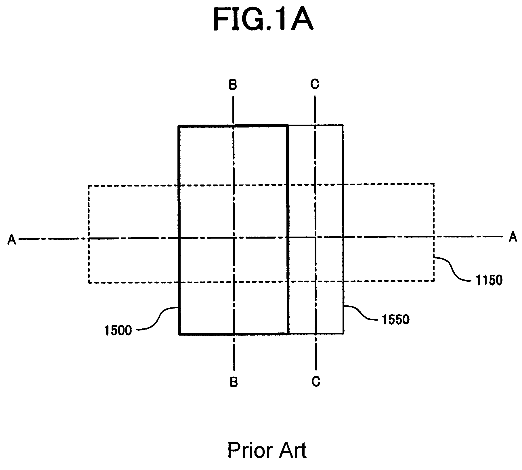
[0083]A second embodiment of the present invention will now be described with reference to FIGS. 26 to 33. These figures are cross-sectional views showing sequential process steps for forming a memory cell array. In each of FIGS. 26 to 33, the illustration (a) on the left-hand side is a cross-sectional view of data file cells, and the illustration (b) on the right-hand side is a cross-sectional view of code file cells. These cross-sectional views are taken along line A-A of FIG. 12 in the channel direction. According to the present invention, the code file portion and the data file portion can be designed to have the same array layout viewed in plan. Therefore, the present embodiment will be described with reference to the layout shown in FIG. 12.

[0084]First, an active region and device isolation regions are formed in the surface of a semiconductor substrate by a common shallow trench isolation (STI) process. It should be noted that these device isolation regions are not shown in th...

third embodiment

[0096]A third embodiment of the present invention will now be described with reference to FIGS. 34 to 42. These figures are cross-sectional views showing sequential process steps for manufacturing a memory cell array. In each of FIGS. 34 to 42, the illustration (a) on the left-hand side is a cross-sectional view of data file cells, and the illustration (b) on the right-hand side is a cross-sectional view of code file cells. These cross-sectional views are taken along line A-A of FIG. 12 in the channel direction. According to the present invention, the code file portion and the data file portion can be designed to have the same array layout viewed in plan. Therefore, the present embodiment will be described with reference to the layout shown in FIG. 12.

[0097]First, an active region and device isolation regions are formed in the surface of a semiconductor substrate by a common shallow trench isolation (STI) process. It should be noted that these device isolation regions are not shown ...


PUM


Abstract

An object of the present invention is to provide an integrated semiconductor nonvolatile storage device that can be read at high speed and reprogrammed an increased number of times.In the case of conventional nonvolatile semiconductor storage devices having a split-gate structure, there is a tradeoff between the read current and the maximum allowable number of reprogramming operations. To overcome this problem, an integrated semiconductor nonvolatile storage device of the present invention is configured such that memory cells having different memory gate lengths are integrated on the same chip. This allows the device to be read at high speed and reprogrammed an increased number of times.

Description

CLAIM OF PRIORITY[0001]The present application claims priority from Japanese application JP 2005-149296 filed on May 23, 2005 and Japanese application JP 2006-129887 filed on May 9, 2006, the contents of which are hereby incorporated by reference into this application.FIELD OF THE INVENTION[0002]The present invention relates to a semiconductor storage device with a nonvolatile memory structure that is stable in operation.BACKGROUND ART[0003]One of the built-in integrated semiconductor storage devices of an LSI is nonvolatile memory. This memory is very important in order to use the LSI in various applications, since it can retain stored data even after power to the LSI is removed.[0004]Nonvolatile semiconductor memory devices employing a floating gate or an insulating film are described in, for example, S. Sze, “Physics of Semiconductor Devices”, 2nd edition, Wiley-Interscience pub., p. 496-506 (Nonpatent Document 1). As is known in the art, unlike floating-gate nonvolatile memory, ...

Claims


Application Information

Patent Timeline
Patent Type & Authority Patents(United States)
IPC IPC(8): H01L21/336
CPCH01L21/28282H01L29/792H01L27/11568H01L27/115G11C16/0425H01L29/40117H10B69/00H10B43/30
Inventor HISAMOTO, DIGHKIMURA, SHIN'ICHIROOKADA, DAISKEYASUI, KAN
Owner RENESAS ELECTRONICS CORP
Why Eureka
Try Eureka