Method for forming inorganic coatings
a technology of inorganic coating and coating layer, which is applied in the field of inorganic coating layer, can solve the problems of inability to meet the needs of patients, affecting the quality of patients' health, and affecting and achieving the effect of improving the quality of patients' health and quality
- Summary
- Abstract
- Description
- Claims
- Application Information
AI Technical Summary
Benefits of technology
Problems solved by technology
Method used
Image
Examples
example i
Mineralization of CaCO3 on Poly(Asparticacid) Soaked Silk Fiber
Materials and Methods
[0074]Cocoons of B. mori silkworm silk were kindly supplied by M. Tsukada, Institute of Sericulture, Tsukuba, Japan. PEO with an average molecular weight of 9×10⁵ g / mol (Aldrich) was used in blending. CaCl2, ammonium carbonate, and poly-L-aspartic acid (sodium salt, MW 11,000) and poly-L-glutamic acid (sodium salt, MW 10900) were obtained from Sigma.
Preparation of Electrospun Fiber Matrix
1. Fiber Matrix Without poly-Asp
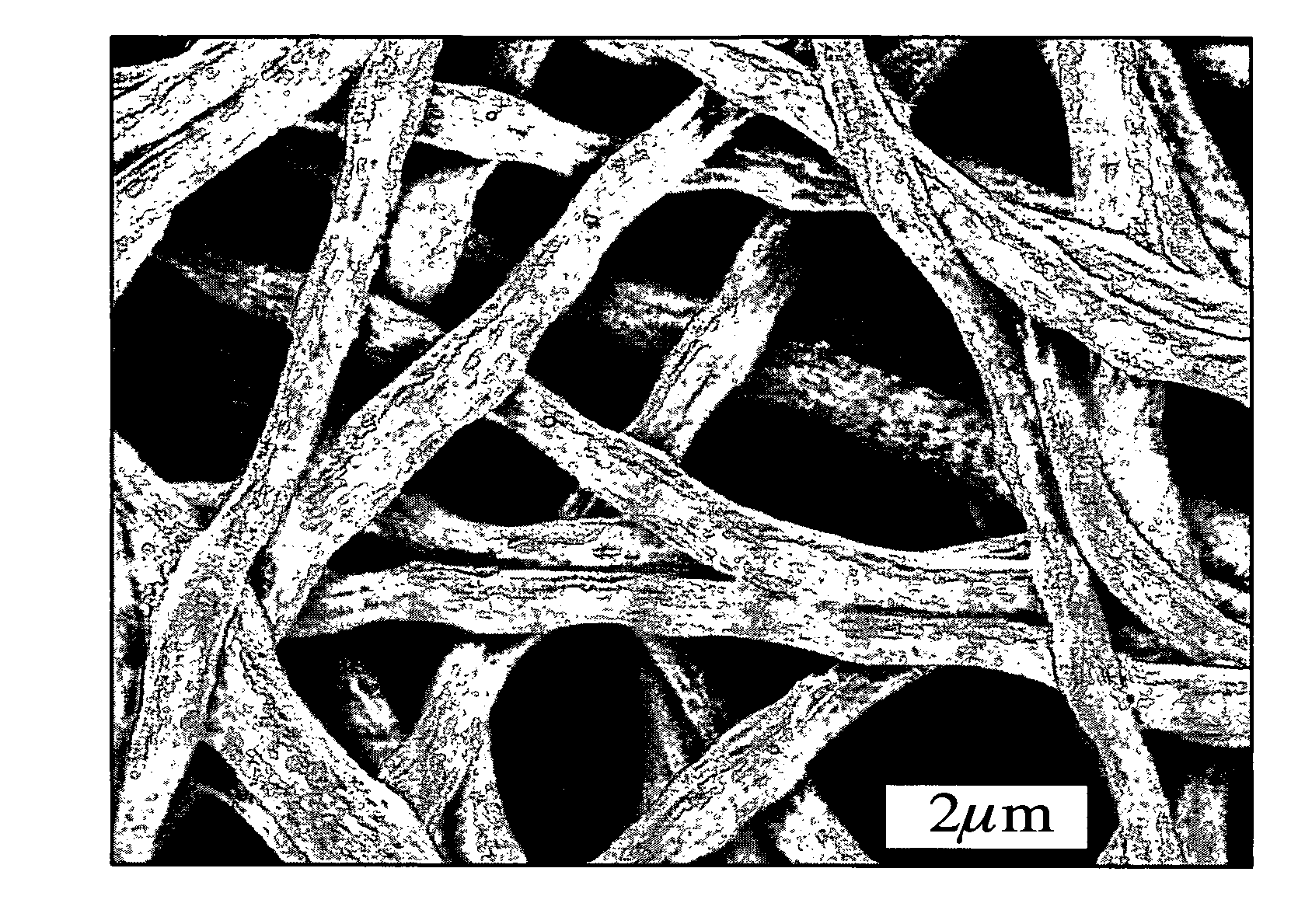
[0075]Silk membranes composed of nanoscale fibers (less than 600 nm in diameter) were fabricated from aqueous silk solutions with PEO by electrospinning as described earlier[6]. The obtained membrane was immersed into a 90 / 10 (v / v) methanol / water solution for 10 min to induce an amorphous to β-sheet conformational transition of electrospun silk fiber and then washed with water for 24 hours at 37° C. to remove PEO. This process was performed in a shaking incubator and shaking speed was ...
case 4
e Growth on Electrospinning Silk Fibers
[0093]An alternative soaking process was used to deposit apatite on silk fibers[20, 21]. First, a silk mat of 5×10 mm was soaked in 200 mM CaCl2 solution (buffered with 50 mM Tris.HCl, pH 7.4 at 37° C.) for predetermined period of time. The silk mat was then transferred to a 120 mM Na2HPO4 solution after excessive moisture was removed by blotting on filter paper and soaked the predetermined period of time. Soaking was repeated for a specific number of cycles.
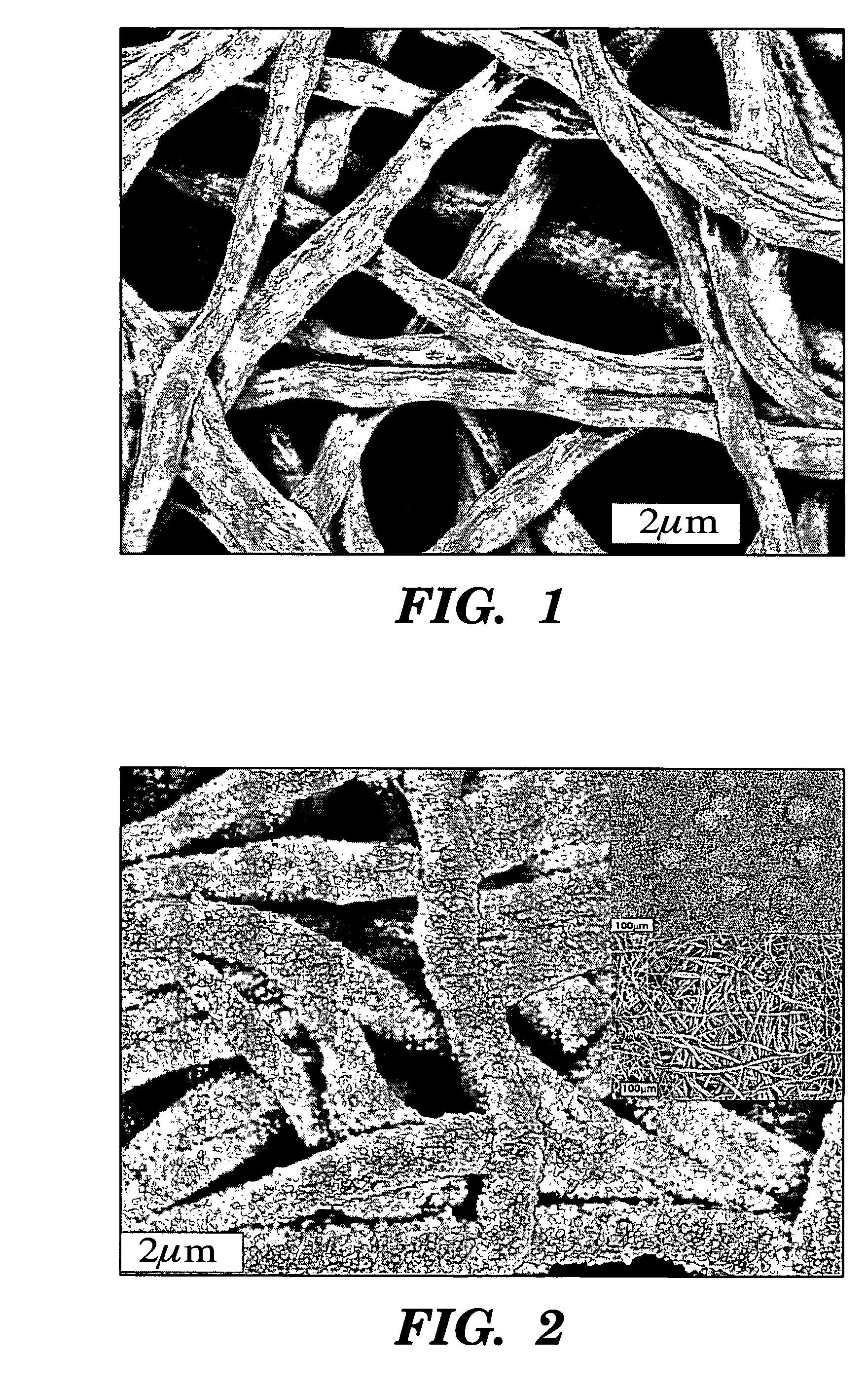
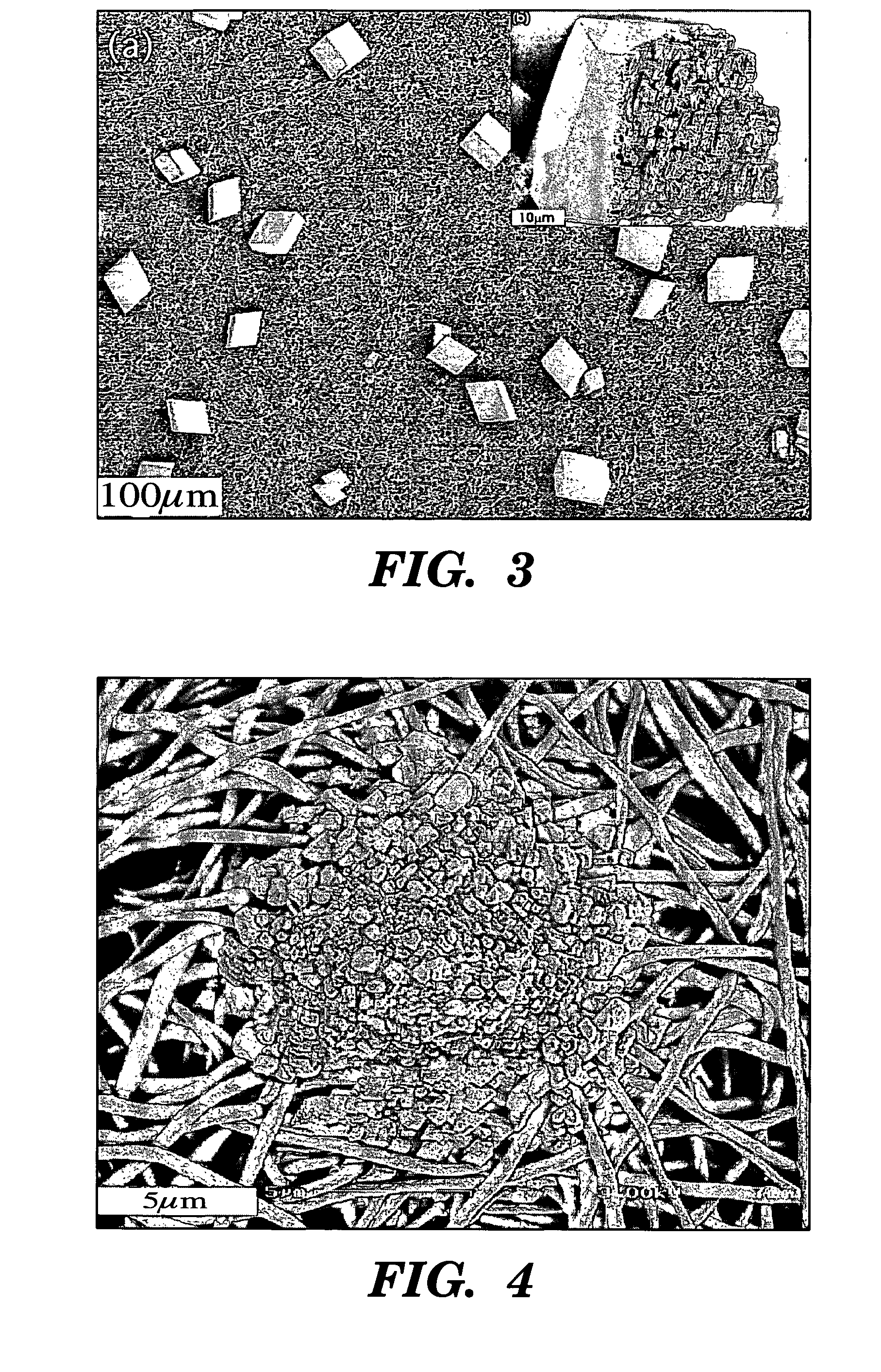
[0094]Aligned growth of the apatite along fiber axes was obtained when the poly-L-aspartic acid concentration was 200 mg / g silk (FIG. 12). As comparison, scattered apatite particles were deposited on silk fibers without poly-L-aspartic acid and only randomly oriented apatite particles formed on silk fibers at a low concentration of poly-L-aspartic acid. FIG. 13 showed the effect of soaking period and cycles on the deposition of apatite on silk fibers. EDS (X-ray Energy-Dispersive Spectrosco...
example ii
Silk Apatite Composites from Electrospun Fibers
[0095]The objective of the present example was to use electrospun silk fibers as nucleation template for growth of apatite as a route to generate new biomaterials with potential utility for bone-related applications. The electrospinning process offers an alternative approach to protein fiber formation that can generate nanometer diameter fibers, a useful feature in some biomaterial and tissue engineering applications due to the increased surface area42-46. Electrospinning has been utilized to generate nanometer diameter fibers from recombinant elastin proteins47, silk-like proteins48-50, silkworm silk fibroin51, type I collagen45,52,53 and spider dragline silk54. If electropsun polymer fibers generate structures suitable for control of functional group patterning, then such templates should be effective for apatite nucleation and crystal growth, leading to new protein-based composites. Since silk fibroin self organizes due to hydrophili...
PUM
| Property | Measurement | Unit |
|---|---|---|
| thick | aaaaa | aaaaa |
| diameter | aaaaa | aaaaa |
| diameter | aaaaa | aaaaa |
Abstract
Description
Claims
Application Information
 - R&D
- Intellectual Property
- Life Sciences
- Materials
- Tech Scout
- Unparalleled Data Quality
- Higher Quality Content
- 60% Fewer Hallucinations
Browse by: Latest US Patents, China's latest patents, Technical Efficacy Thesaurus, Application Domain, Technology Topic, Popular Technical Reports.
© 2025 PatSnap. All rights reserved.Legal|Privacy policy|Modern Slavery Act Transparency Statement|Sitemap|About US| Contact US: help@patsnap.com


