
Electromagnetic interference shielding polymer composites and methods of manufacture

a technology of electromagnetic interference and polymer composites, applied in the field of polymer composites, can solve the problems of device performance, total failure, and electromagnetic sensitiveness of electronic devices, and achieve the effects of high permittivity, high permittivity polymer, and effective operation over a wide range of frequencies

Inactive Publication Date: 2010-10-19
GE GLOBAL SOURCING LLC
View PDF13 Cites 57 Cited by
  • Summary
  • Abstract
  • Description
  • Claims
  • Application Information

AI Technical Summary

Benefits of technology

The present invention provides an effective electromagnetic interference shielding composite that works over a wide range of frequencies. This composite includes a high permittivity polymer, magnetic particles, and dielectric particles dispersed within the polymer. The invention also includes an article comprising a device susceptible to electromagnetic radiation and a shielding material disposed to shield the device from electromagnetic radiation, which also includes the same components as the composite.

Problems solved by technology

Electrical and electronic devices are often sensitive to electromagnetic interference (EMI) that is present in the environment due to many sources.
EMI often disrupts the device performance and may lead to total failure.
However, they are bulky, not very effective at higher frequencies, and are difficult to form into highly convoluted shapes.
Dielectric or magnetic materials have intrinsic impedance different from that of free space (377 Ohms), which causes an electrical mismatch at the air / shield interface.
Conducting particles, on the other hand, contribute to the conductivity of the absorbing layer and may lead to electrical shortage or shock.
These materials are only effective in attenuating EMI at very large thicknesses.

Method used


Image

  • Electromagnetic interference shielding polymer composites and methods of manufacture
  • Electromagnetic interference shielding polymer composites and methods of manufacture
  • Electromagnetic interference shielding polymer composites and methods of manufacture

Examples


example 1

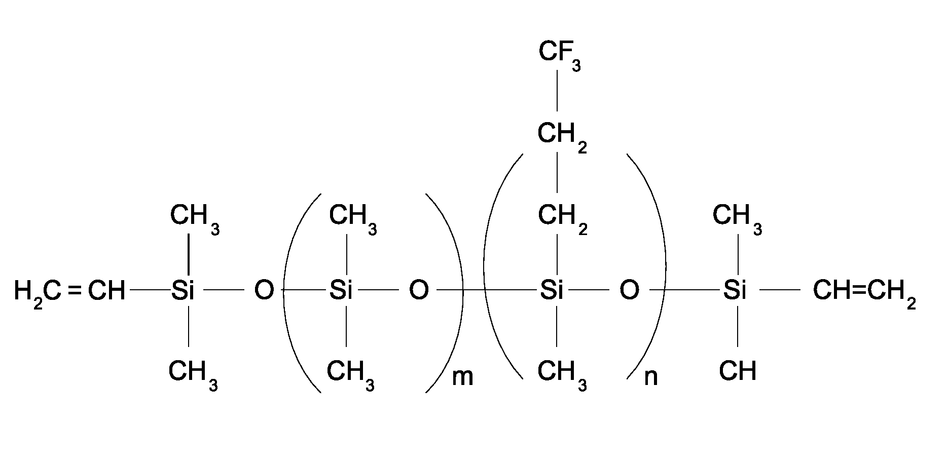
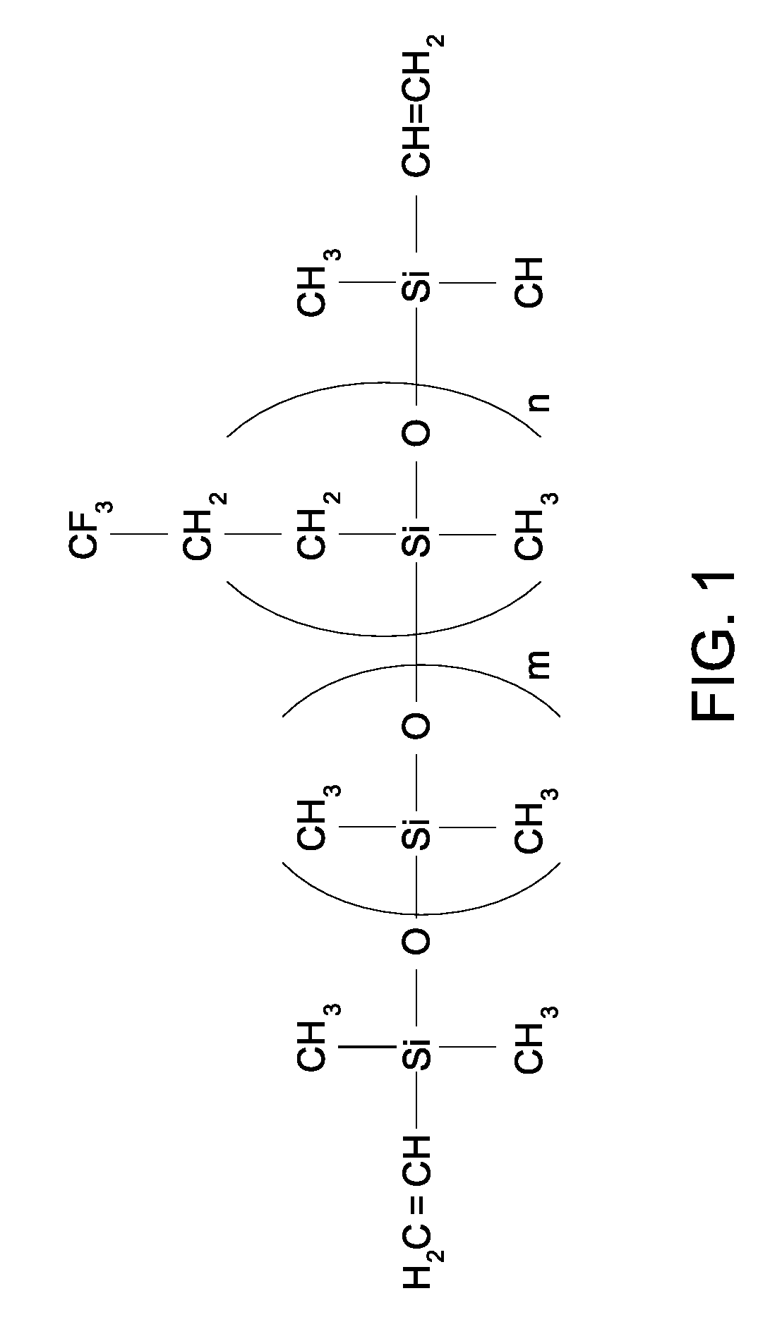
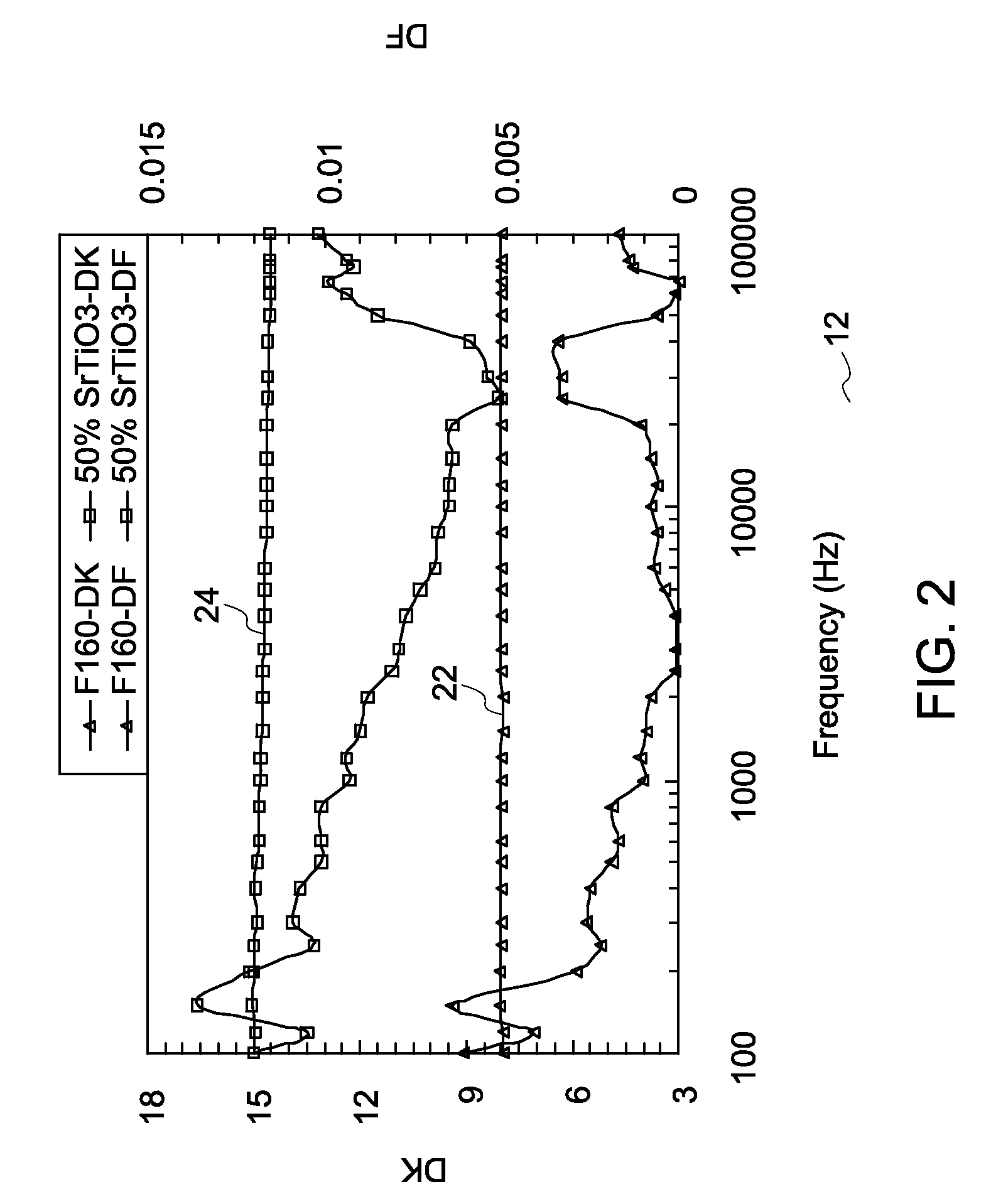
[0037]20 grams of fluorosilicone (chemical structure shown in FIG. 1) was prepared as a base resin. Homopolymer silicone resin (with m=0 in the chemical structure shown in FIG. 1) is a gel at room temperature and was diluted in MEK (methyl ether ketone) to form 20 wt % solution. 20 g of SrTiO3 nanoparticles (with mean particle size of 40 nanometers) were dispersed into the solution with high shear mixing. (Note: If sonication is preferred for better particle dispersion, the resin needs to be diluted further with MEK to adjust the viscosity to ˜30 cps.) The silicone resin was cured by adding 5 wt % peroxide (dicumyl peroxide) with good mixing. The solvent was evaporated under vacuum and silicone resin was cured at 180° C. for 2 hours. As an exemplary alternative, the silicone resin may be cured by adding 1.2 wt % silicone hydride and 4 ppm Pt catalyst, followed by solvent evaporation at room temperature under vacuum and 180° C. curing for 30 min. The dielectric permittivity (Dk) and ...

example 2

[0038]100 grams of tetraglycidyl methylene dianiline epoxy resin was pre-heated to 80° C. to reduce the viscosity to 12O19 powder with particle size of less than 100 nanometers was dispersed into the epoxy resin with high shear mixer. After vacuum degassing, the sample was thermally cured at 180° C. for two hours. The magnetic permeability of the composite is plotted in FIG. 3 as a function of frequency and dielectric permittivity and dielectric loss factor are plotted in FIGS. 4 and 5, respectively. The plots show the magnetic permeability and dielectric permittivity of the composite are in the optimal range for EMI absorbing applications.


PUM

PropertyMeasurementUnit
particle sizeaaaaaaaaaa

Abstract

An electromagnetic interference shielding composite is provided. The electromagnetic interference shielding composite comprises: a high permittivity polymer having a permittivity of at least about 5; a plurality of magnetic particles dispersed within the high permittivity polymer; and a plurality of dielectric particles dispersed within the high permittivity polymer. In another embodiment, an article comprising a device susceptible to electromagnetic radiation and a shielding material disposed to shield the device from electromagnetic radiation is provided. The shielding material comprises, a high permittivity polymer; a plurality of magnetic particles dispersed within the high permittivity polymer; and plurality of dielectric particles dispersed within the high permittivity polymer.

Description

BACKGROUND[0001]The invention relates generally to polymer composites. More specifically, to polymer composites capable of absorbing electromagnetic interference signals. The invention also relates to articles comprising polymer composites capable of absorbing electromagnetic interference signals.[0002]Electrical and electronic devices are often sensitive to electromagnetic interference (EMI) that is present in the environment due to many sources. EMI sources may be self-induced due to noisy components (e.g. transistors), or externally induced by electronic equipment (e.g., fluorescent lighting, motors, radar transmitters). Electromagnetic energy may propagate by conduction through wires or conductive surfaces or through reactive coupling (inductive or capacitive-crosstalk between wires), or radiation. EMI often disrupts the device performance and may lead to total failure.[0003]To reduce these problems, it is a common practice to shield the devices from external EMI. Conventionally...

Claims


Application Information

Patent Timeline
Patent Type & Authority Patents(United States)
IPC IPC(8): H01B1/02H01B1/04H01B1/12
CPCH05K9/0083
Inventor TAN, DANIEL QICAO, YANGIRWIN, PATRICIA CHAPMAN
Owner GE GLOBAL SOURCING LLC
Learn More