Lethal and sublethal damage repair inhibiting image guided simultaneous all field divergent and pencil beam photon and electron radiation therapy and radiosurgery

a radiation therapy and electron radiation therapy technology, applied in radiation therapy, x-ray/gamma-ray/particle-irradiation therapy, therapy, etc., can solve the problems of poor tumor cell kill, inefficient radiation therapy method, poor patient comfort, etc., to shorten the time required and increase patient comfort

Inactive Publication Date: 2010-11-16
SAHADEVAN VELAYUDHAN
View PDF10 Cites 66 Cited by
  • Summary
  • Abstract
  • Description
  • Claims
  • Application Information

AI Technical Summary

Benefits of technology

[0099]In this all field simultaneous radiation therapy system for daily-fractionated radiation therapy and single dose radiosurgery, multiple treatment heads with photon beam generating target is mounted isocentrically on to a rotating or stationary gantry. Accelerated electron beam from single or multiple S-band, C-band or X-band microwave powered linear accelerators is made to pass through interconnecting beam lines by bending and deflection magnets. Like in a conventional medical linear accelerator, the photon beam transmitted from the target and passed through the flattening filter provides divergent therapeutic photon beam. The flattening filter is removed to give pencil beams. Likewise, as in conventional medical linear accelerators, the electron beam intended for therapeutic purpose does not pass through the photon-generating target. Combined divergent beams and pencil beam mode of treatment is used to enhance intensity modulation within a treatment field. The radiation intensity within a field is enhanced as needed with smaller pencil beam fields within a larger divergent beam field. Combined divergent beam and pencil beam also allows treatment of a field with varying energy radiating beams. The multiple parallel opposing treatment heads are mounted at their respective parallel opposing angles around the treatment table.
[0100]The beam from the main beam line is deflected towards the target by beam steering with smaller deflection magnets, which eliminates the larger bending magnet in ancillary treatment heads. It further reduces the scatted component of the head leakage radiation, which helps to reduce the radiation to the normal tissue. It reduces the incidence of acute and late radiation toxicities and the late occurring second primary tumors.
[0101]The beam on time to complete the entire treatment of eight fields IMRT is reduced to about less than 10 seconds. With simultaneous multiple beam iso centric treatment setup to treat a patient, the entire patient setup time for IMRT is reduced to about 5 minutes. The treatment time to complete a single dose radiosurgery with multiple fields and multiple isocenters is only about 1 min or less. The patient setup time for radiosurgery may vary but since the treatment is rendered by simultaneous multiple isocentric beams the overall patient setup time is also reduced to about 15 min or less. The short duration beam on radiosurgery minimizes or eliminates the uncertainties associated with organ movements.

Problems solved by technology

Moreover, all the treatment plans that look as good in the computer color screen may not be as good and accurate on the patient.
Radiobiologically, its tumor cell kill is poor since it is dominated by αD1.
It is an inefficient method of radiation therapy.
The disadvantages of 60Co includes its low energy, low dose rate, lower SSD factor when the machine is calibrated at 80.5 cm SSD and the treatment SSD 100.5 cm.
There is also the need to replace the Cobalt-60 source frequently due to its lower half-life and there are serious difficulties associated with its disposal and health hazards.
It is still too high.
This increases the scattered and leakage radiation is increased which increases the dose to normal tissue.
In the case of Co-60 machines where lower MV and shorter SSD are used, this higher d-max dose and the scattered and leakage radiation reaching the normal tissue when IMRT like treatment is elected will be prohibitively high.
It is not feasible with any other present systems.
The limiting factor is the technological difficulties and precise field defining for such treatment.
When the Tomotherapy is used with its maximum field size of 5×5 cm, it increases its leakage radiation significantly.
Hence there is no practical advantage from smaller slice thickness treatment with this machine.
Thus the conventional tomotherapy is associated with high leakage and scattered radiation.
In addition there is increased leakage and scattered radiation from increased monitor units used in IMRT.
It has a short latency period of 2-4 years and has no effective traditional chemotherapy.
17, p 569, 1999) In this scenario, an increase in leakage and scattered radiation to the normal tissue form IMRT is not a desirable option.
Damage to normal tissue increases with increasing integral dose.
It causes higher radiation induced acute and late toxicities.
This further reduces radiation to the normal tissue while increasing its efficiency and efficacy
It is much more uncomfortable to the patient if the treatment lasts for 2-3 hours as in conventional multiple field setup radiosurgery.

Method used


Image

  • Lethal and sublethal damage repair inhibiting image guided simultaneous all field divergent and pencil beam photon and electron radiation therapy and radiosurgery
  • Lethal and sublethal damage repair inhibiting image guided simultaneous all field divergent and pencil beam photon and electron radiation therapy and radiosurgery
  • Lethal and sublethal damage repair inhibiting image guided simultaneous all field divergent and pencil beam photon and electron radiation therapy and radiosurgery

Examples


Embodiment Construction

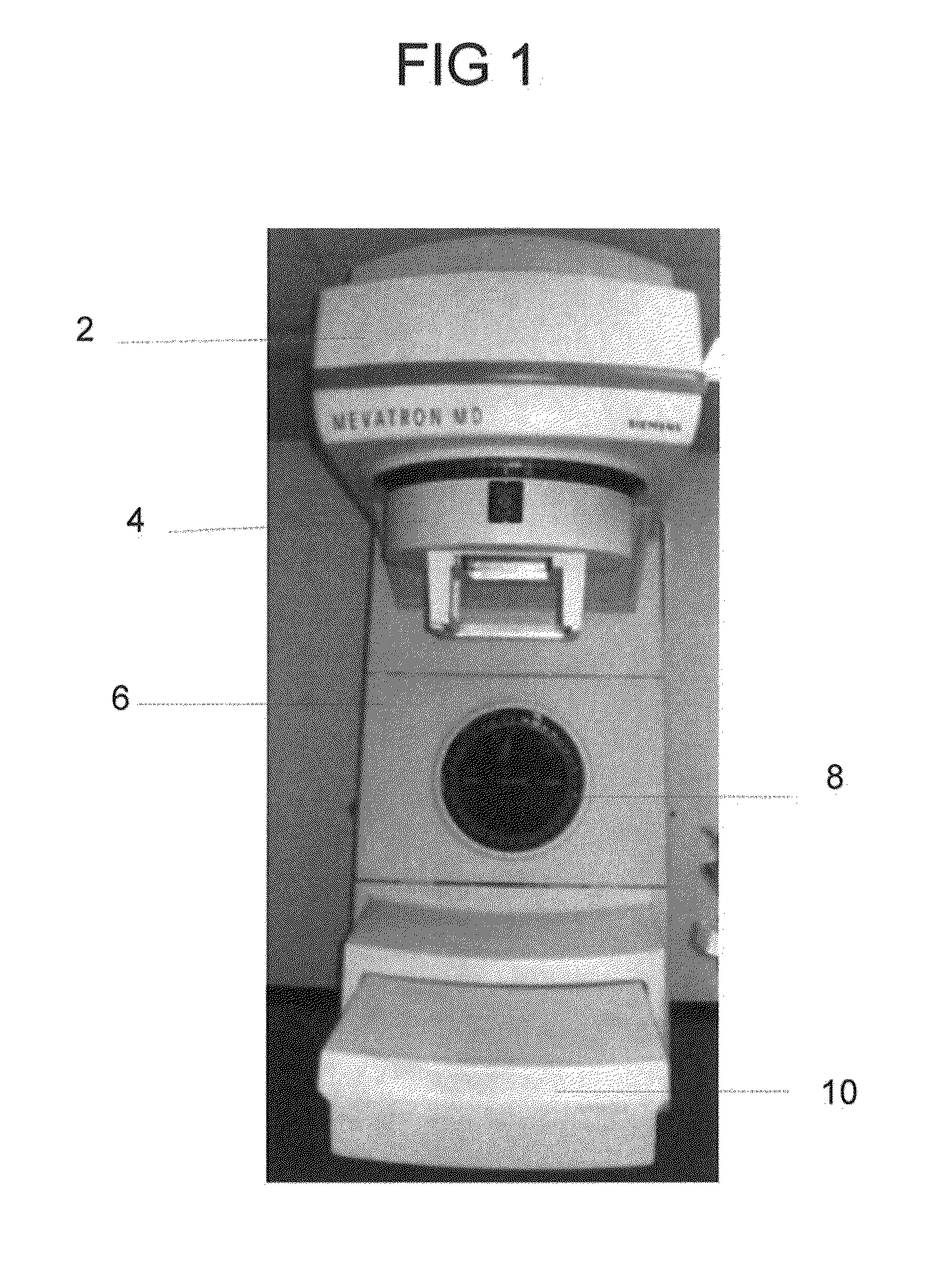
[0231]In FIG. 1 a conventional medical accelerator with its rotating gantry and the counter weight is shown. Its treatment head 2, collimator and accessory holder 4, gantry 6, protractor 8 and the counterweight—beam shield 10 are modified and adapted to use in this invention.

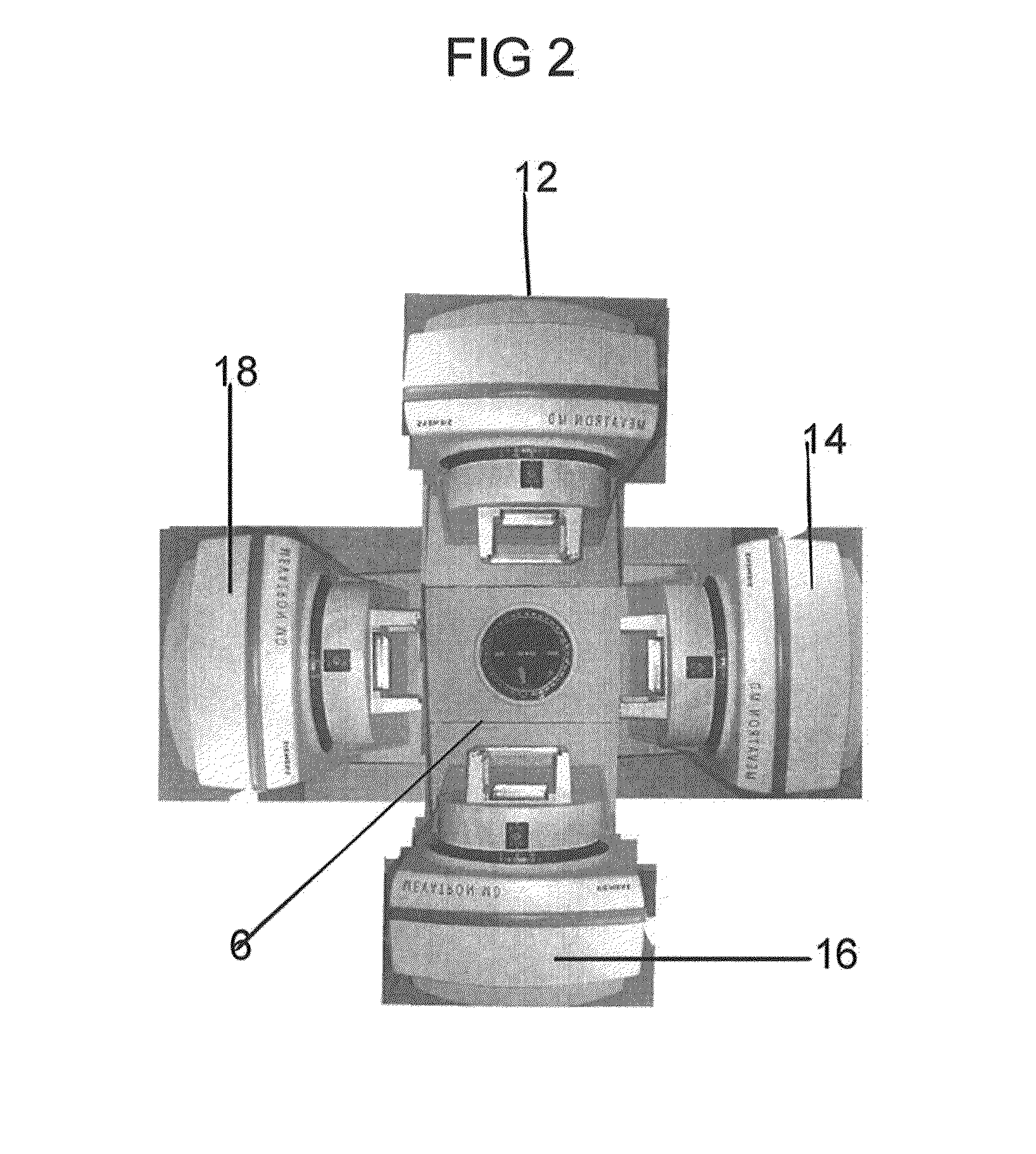
[0232]FIG. 2 shows four conventional medical accelerators combined on to a gantry system for four field simultaneous radiation therapy and radiosurgery. These accelerators are single or dual energy accelerators. They are selected as one with a single energy, namely 6 MV or with dual energies of 2 and 6 or 4 and 6 MV. The second accelerator provides a single 8 or 10 MV beam or dual energies of 4 and 8 or 6 and 10 or higher MV. Based upon the need, any other such varying energy accelerator combination is selected. The accelerator and its waveguide 12, is mounted on to a fully or partially rotating gantry, 6. The beam shield, 10, is replaced with a treatment head which also function as a counterweight. The four suc...


PUM


Abstract

A medical accelerator system is provided for simultaneous radiation therapy to all treatment fields. It provides the single dose effect of radiation on cell survival. It eliminates the inter-field interrupted, subfractionated fractionated radiation therapy. Single or four beams S-band, C-band or X-band accelerators are connected to treatment heads through connecting beam lines. It is placed in a radiation shielding vault which minimizes the leakage and scattered radiation and the size and weight of the treatment head. In one version, treatment heads are arranged circularly and connected with the beam line. In another version, a pair of treatment heads is mounted to each ends of narrow gantries and multiple such treatment heads mounted gantries are assembled together. Electron beam is steered to all the treatment heads simultaneously to treat all the fields simultaneously. Radiating beam's intensity in a treatment field is modulated with combined divergent and pencil beam, selective beam's energy, dose rate and weight and not with MLC and similar devices. Since all the treatment fields are treated simultaneously the dose rate at the tumor site is the sum of each of the converging beam's dose rate at depth. It represents the biological dose rate. The dose rate at d-max for a given field is the individual machine dose rate. Its treatment options includes divergent or pencil beam modes. It enables to treat a tumor with lesser radiation toxicities to normal tissue and higher tumor cure and control.

Description

CROSS-REFERENCE TO RELATED APPLICATIONS[0001]This application claims priority to Provisional Patent Application No. 60 / 790,192, filed on Apr. 6, 2006, the contents of which are incorporated herein.FIELD OF INVENTION[0002]This present invention relates to cancer treatment by all field's simultaneous radiation therapy with multiple medical accelerators to improve tumor cure and control while minimizing lower dose radiation to normal tissue.BACKGROUND OF THE INVENTION[0003]To minimize immediate and late toxic effects of radiation to normal tissue, most often radiation is administered through multiple treatment fields. Smaller fractions of daily prescribed dose of radiation are given to each of the treatment fields. The radiation from such multiple fields converges at the tumor site to give the daily fractionated dose of radiation. The sum of the radiation dose from each of such smaller fields makes the prescribed daily dose of radiation to the tumor.[0004]Radiating a tumor by multiple ...

Claims


Application Information

Patent Timeline
Patent Type & Authority Patents(United States)
IPC IPC(8): A61N5/10
CPCA61N5/1081A61N5/1084A61N5/1042A61N2005/1061A61N2005/1089
Inventor SAHADEVAN, VELAYUDHAN
Owner SAHADEVAN VELAYUDHAN
Why Eureka
Try Eureka