Aluminum-silicon carbide composite

a technology of silicon carbide and composite materials, which is applied in the field of aluminum/silicon carbide composites, can solve the problems of failure or fracture of semiconductors on circuits, increasing heat generation amounts, and increasing heat generation, and achieves good heat dissipation properties after soldering to ceramic circuit plates. , the effect of low thermal expansion

Active Publication Date: 2010-11-23
DENKA CO LTD
View PDF8 Cites 0 Cited by
  • Summary
  • Abstract
  • Description
  • Claims
  • Application Information

AI Technical Summary

Benefits of technology

[0019]The aluminum / silicon carbide composite of the present invention has properties such as low thermal expansion and high thermal conductivity. By preliminarily forming or machining one principal plane of a flat silicon carbide porous body into a convex shape before infiltration with an aluminum alloy and further machining the surface aluminum alloy layer after infiltration with an aluminum alloy, heat dissipation properties after soldering to a ceramic circuit plate tend to be good as compared with a conventional method of imparting bow. The composite can be easily processed into a predetermined shape, the shape of the radiation plane is less likely to be distorted, and occurrence of local irregular color in the outer appearance can be prevented, and accordingly the composite is suitable as a base plate for a ceramic circuit plate on which semiconductor components are to be mounted, for which high reliability is particularly required.

Problems solved by technology

At present, along with high integration and miniaturization of semiconductor devices, the heat generation amount is increasingly high, and the problem is how effectively heat is dissipated.
However, in such a structure, if a heat load is applied for example, cracking resulting from the difference in the coefficient of thermal expansion between the base plate and the ceramic circuit plate results in the solder layer and as a result, heat dissipation tends to be insufficient, thus leading to malfunction or fracture of the semiconductor on the circuit.
However, with respect to the bow obtained by such a method, the dispersion of the amount of bow tends to be large, and the shape of the bow is not constant, and accordingly, the quality is not stable.
However, in the case of an aluminum / silicon carbide composite, the material is very hard, and accordingly, grinding employing a tool of e.g. diamond is required, whereby the processing time tends to be long, and the cost tends to be expensive.
However, of the base plate produced by the above method, the center portion of the aluminum alloy layer tends to be thick after machining.
Accordingly, when the base plate is soldered to the ceramic circuit plate to assemble a power module, the shape at the center portion of the radiation plane may be distorted depending upon the disposition of the ceramic circuit plate, a gap is formed between the base plate and the heat dissipation fin, and no sufficient heat dissipation properties can be exhibited in some cases.
Further, in the above method, in order to control the thickness of the aluminum alloy layer on both principal planes, a high purity aluminum plate having a melting point higher than that of an aluminum alloy to be used for infiltration, is used in some cases, and local difference in the color tone may result due to the reaction between the high purity aluminum and the aluminum alloy layer having a low melting point at the time of infiltration in some cases.

Method used


Image

  • Aluminum-silicon carbide composite
  • Aluminum-silicon carbide composite

Examples


example 1

[0050]700 g of SiC powder A (manufactured by Pacific Rundum Co., Ltd., NG-220, average particle size: 60 μm), 300 g of SiC powder B (manufacture by YAKUSHIMA DENKO CO., LTD., GC-1000F, average particle size: 10 μm) and 100 g of a silica sol (manufactured by Nissan Chemical Industries, Ltd., SNOWTEX) were weighed, and they were mixed by a stirring mixer for 30 minutes and press molded under a pressure of 10 MPa into a flat plate having dimensions of 185 mm in length×135 mm in width×5.0 mm in thickness.

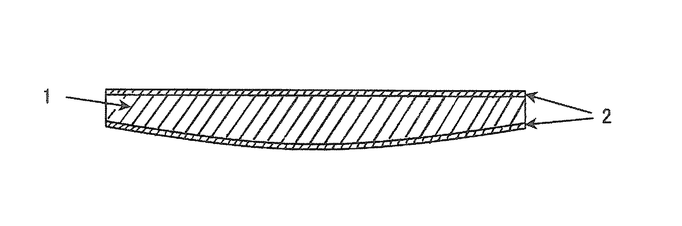
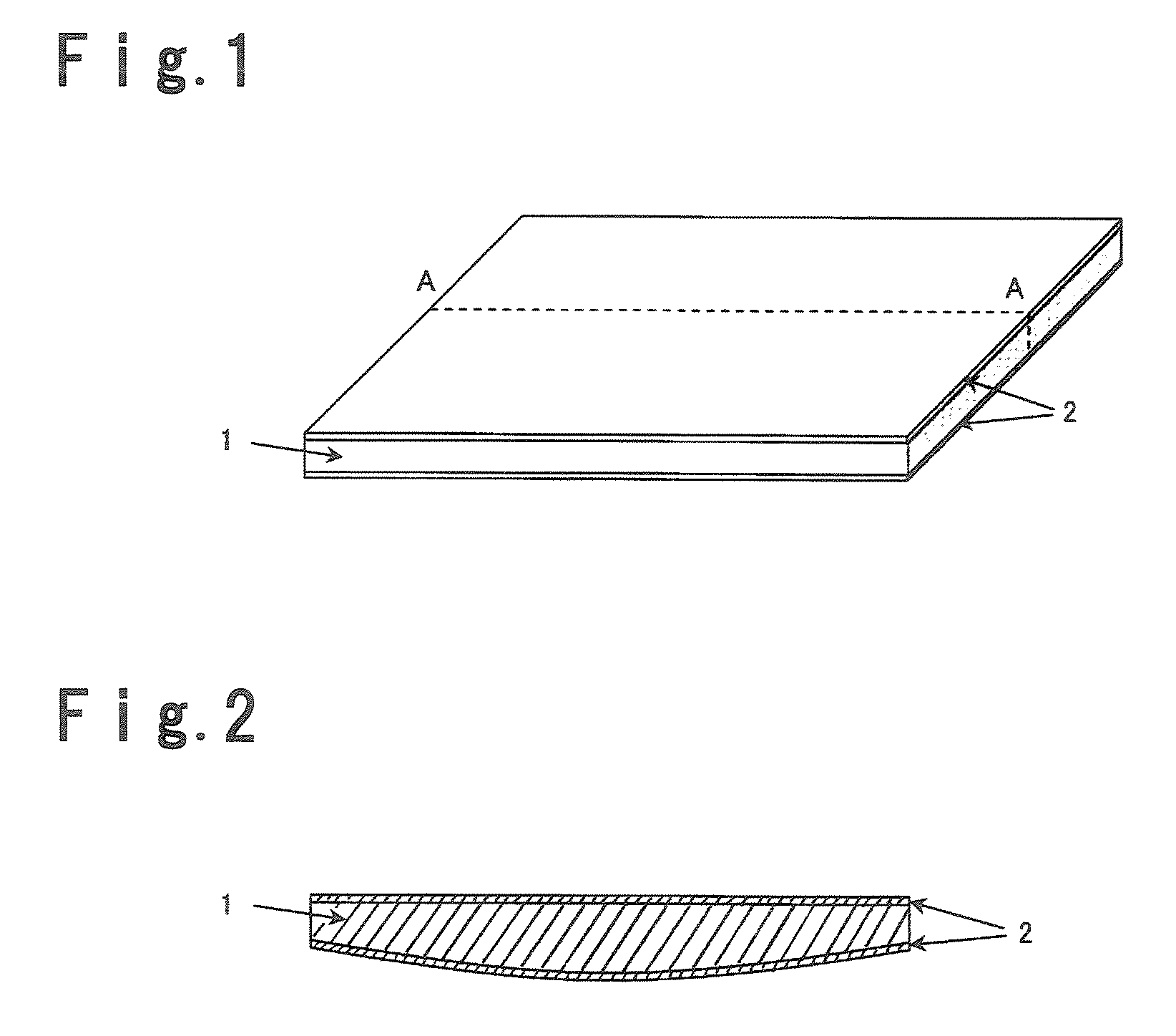
[0051]The obtained molded product was fired in atmospheric air at 900° C. for 2 hours to obtain a SiC preform having a relative density of 65 vol %, and one principal plane of the SiC preform was processed by a lathe turning machine to a convex spherical shape with a bow of 200 μm per 200 mm, and the thickness at the center portion was adjusted to 4.6 mm.

[0052]The obtained SiC preform was put in an iron frame of 185 mm in length×135 mm in width×5.2 mm in height, provided with a gate thr...

examples 2 to 9

[0059]An aluminum / silicon carbide composite was prepared, processed and evaluated in the same manner as in Example 1 except that the thickness of the alumina fibers on the flat plane was changed to 0.1 mm so that the average thickness of the aluminum alloy layer would be 100 μm and that the spherical plane was ground by 300 μm after infiltration with the aluminum alloy (Example 2), that the thickness of the aluminum fibers on the flat plane was changed to 0.3 μm so that the average thickness of the aluminum alloy layer would be 300 μm and that the spherical plane was ground by 100 μm after infiltration with the aluminum alloy (Example 3), that the thickness of the aluminum fibers on the flat plane was changed to 0.05 mm so that the average thickness of the aluminum alloy layer would be 50 μm and that the spherical plane was ground by 350 μm after infiltration with the aluminum alloy (Example 4), that the thickness of the alumina fibers on the flat plane was changed to 0.35 mm so tha...

examples 10 to 16

[0060]An aluminum / silicon carbide composite was prepared and evaluated in the same manner as in Example 1 except that the content of the alumina fibers was 3 mass % (Example 10), that the content of the alumina fibers was 45 mass % (Example 11), that the content of the alumina fibers was 5 mass % (Example 12), the content of the alumina fibers 40 mass % (Example 13), that no alumina fibers were disposed on both planes of the SiC preform (Example 14), that spherical alumina particles (manufactured by Sumitomo Chemicals Co., Ltd., alumina CB-10 grade, purity 99.9%) were used in a content of 35 mass % instead of the alumina fibers (Example 15), and that crushed alumina particles (manufactured by SHOWA DENKO K.K., alumina AL-15-H grade, purity 99.9%) were used in a content of 35 mass % instead of the alumina fibers. The results are shown in Tables 1 and 2.

[0061]

TABLE 1Dispersion{(Difference inof Al layeraverage thick-Differencethickness (μm)ness betweenAverage thicknessin average(Maximu...


PUM

PropertyMeasurementUnit
thicknessaaaaaaaaaa
thicknessaaaaaaaaaa
pressureaaaaaaaaaa

Abstract

An aluminum / silicon carbide composite prepared by infiltrating a flat silicon carbide porous body with a metal containing aluminum as the main component, including an aluminum alloy layer made of a metal containing aluminum as the main component on both principal planes, and one principal plane is bonded to a circuit plate and the other principal plane is utilized as a radiation plane. The silicon carbide porous body is formed or machined into a convexly bowed shape, and after infiltration with the metal containing aluminum as the main component, the aluminum alloy layer on the radiation plane is further machined to form the bow shape. The aluminum / silicon carbide composite is suitable as a base plate for a ceramic circuit plate on which semiconductor components are mounted, for which high reliability is required.

Description

TECHNICAL FIELD[0001]The present invention relates to an aluminum / silicon carbide composite suitable as a base plate for a circuit plate. In the present invention, the major axis represents a diagonal in a case where the shape of a flat plate is a tetragon, a diameter in a case of a circle, a major axis in the case of an ellipse and the longest axis in the case of other shapes.BACKGROUND ART[0002]At present, along with high integration and miniaturization of semiconductor devices, the heat generation amount is increasingly high, and the problem is how effectively heat is dissipated. And, a substrate which comprises a ceramic circuit plate comprising a ceramic substrate having high insulating properties and high thermal conductivity, such as an aluminum nitride substrate or a silicon nitride substrate, and a metal circuit made of copper or aluminum formed on the surface of the ceramic substrate, and which has a base plate made of copper or aluminum, as a heat dissipation plate, forme...

Claims


Application Information

Patent Timeline
Patent Type & Authority Patents(United States)
IPC IPC(8): B32B5/14B22F3/00G11B11/105B32B3/26B32B5/22B32B9/00
CPCC04B41/009C04B41/88H01L23/13H01L23/142H01L23/15H01L23/3733H05K1/05C04B41/5155C04B35/565C04B38/00C04B41/4521C04B41/4523Y10T428/12007C04B2111/00844H05K1/0284H05K1/0306H05K2201/0116H05K2201/09018Y10T428/26H01L2924/0002H01L2924/00Y10T428/249957Y10T428/249971Y10T428/249987Y10T428/249974Y10T428/249986Y10T428/24999H01L23/373
Inventor IWAMOTO, GOHHIROTSURU, HIDEKIHIRAHARA, KAZUNORI
Owner DENKA CO LTD
Why Eureka
Try Eureka