Chemical mechanical polishing slurry composition including non-ionized, heat activated nano-catalyst and polishing method using the same

Active Publication Date: 2011-02-15
DONGJIN SEMICHEM CO LTD
View PDF26 Cites 7 Cited by
  • Summary
  • Abstract
  • Description
  • Claims
  • Application Information

AI Technical Summary

Benefits of technology

[0015]The prior chemical mechanical polishing slurry composition for polishing tungsten (W) contains a large amount of metal (iron) ions. For this reason, after a process of polishing a wafer, the wafer surface can be contaminated by a large amount of metal (iron) ions, and slurry remaining on the wafer can additionally corrode the tungsten plug, thus causing a short circuit in the plug. Also, the substrate can be contaminated by a large amount of metal ions, and an organic additive must be added to the composition in order to reduce the level of contamination by metal ions. On the contrary, in the chemical mechanical polishing slurry composition according to the present invention, metal (ion) ions are not present in the slurry, and thus the m

Problems solved by technology

In miniaturization of semiconductor chips, simply decreasing the size of devices has limitations, and thus studies on multilayer interconnect structures for forming each device in a multilayer structure have recently been actively conducted.
However, because the metal layers are not easy to polish due to their high strength, in order to effectively polish the metal layer, the polishing process must be carried out after oxidizing the metal layers in the form of metal oxides having relatively low strength.
However, conventional chemical mechanical polishing slurry compositions have a shortcoming in that the efficiency of a chemical conversion process of oxidizing metal layers in the form of metal oxides is insufficient.
However, because the disclosed method uses a large amount of iron salt, a metal layer bei

Method used


Image

  • Chemical mechanical polishing slurry composition including non-ionized, heat activated nano-catalyst and polishing method using the same
  • Chemical mechanical polishing slurry composition including non-ionized, heat activated nano-catalyst and polishing method using the same
  • Chemical mechanical polishing slurry composition including non-ionized, heat activated nano-catalyst and polishing method using the same

Examples


examples 19 to 21

Tests for Polishing Performance of Metal Silicides (MSi) with Different Transition Metals

[0047]The polishing performance of ferrosilicon and metal silicides (MSi) with different transition metals was comparatively tested, and the test results are shown in Table 4 below. As can be seen from the results in Table 4, the removal rate of the tungsten substrate in the cases of manganese silicide and cobalt silicide was reduced compared to the case of nano-ferrosilicide, but the polishing function thereof could be confirmed. Accordingly, it could be found that other transition metal silicides such as manganese silicide and cobalt silicide, in addition to ferrosilicide as the non-ionized heat-activated nano-catalyst, also belong to a class of non-ionized, heat-activated nano-catalysts which release electrons and holes by energy generated in chemical mechanical polishing processes.

[0048]The polishing performance tests were carried out using the same polishing machine, method and conditions a...

experimental examples 1 to 3

Experiments of Reactivity by Thermal Energy

[0050]To examine the reactivity between the oxidizing agent (hydrogen peroxide) and the catalyst, 3.0 wt % of the oxidizing agent was added to each of an aqueous solution containing pure deionized water and 0.0017 wt % of nano-ferrosilicon (Fe content: 8 ppm) as the non-ionized, heat-activated nano-catalyst according to the present invention, and an aqueous solution containing 0.0434 wt % of ferric nitrate ((Fe(NO3)3; Fe content: 60 ppm) as the prior catalyst, and the states (the change in color caused by reaction with the oxidizing agent, and the generation of bubbles) of the aqueous solutions were observed. Also, the aqueous solutions were heated to 60° C., and the oxidizing agent was then added thereto, after which the states of the aqueous solutions were observed. The observation results are shown in Table 5 below.

[0051]

TABLE 5Imme-diatelyWithinBeforeAfter Immediately30 AdditionAdditionAfterminsofofHeatingAfterOxidizingOxidizing toHeati...

experimental example 4

Relationship Between Polishing Temperature and Removal Rate

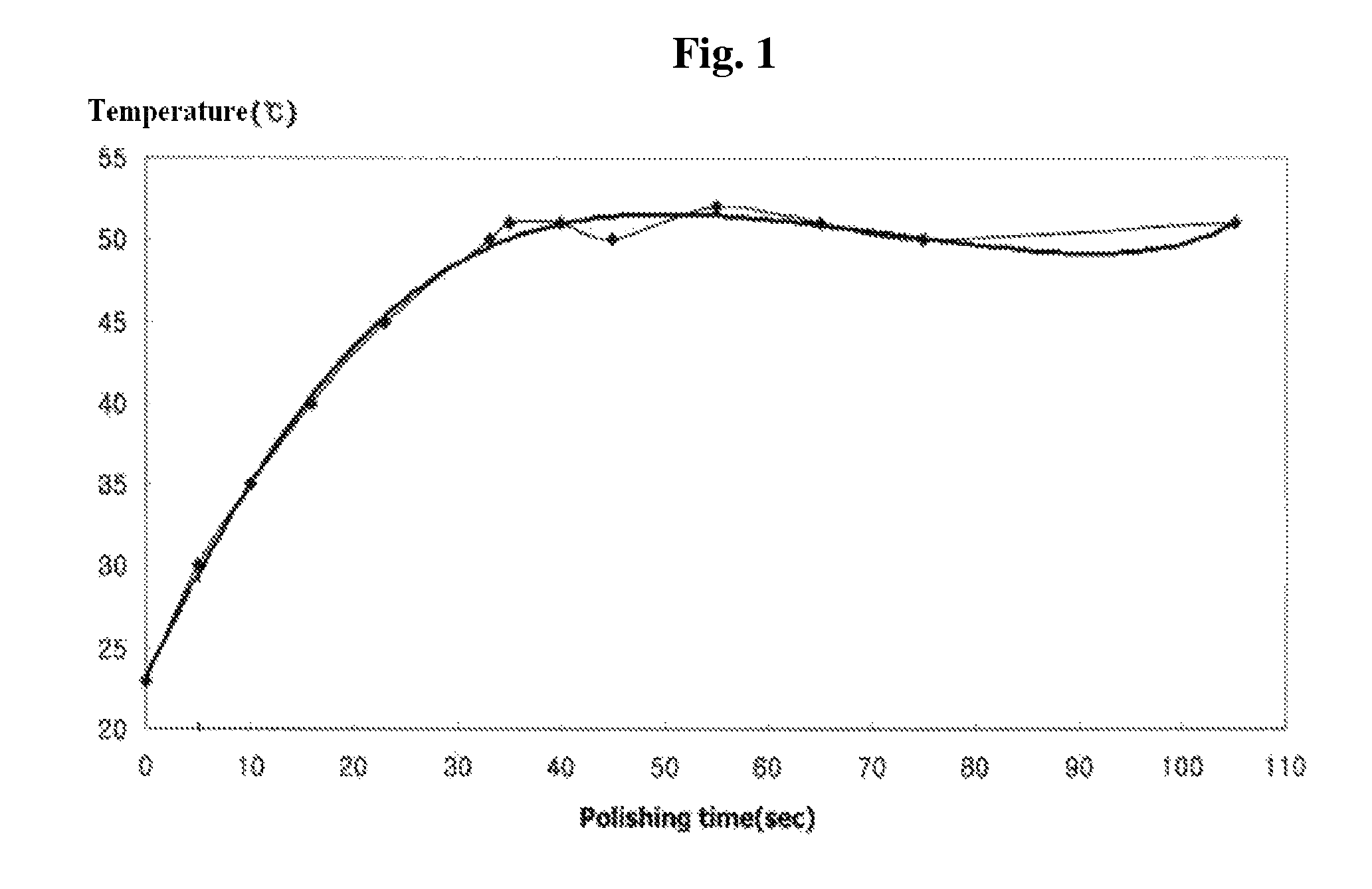
[0053]In order to examine the relationship between polishing temperature and removal rate, a wafer having a 8,000 Å-thick tungsten (W) CVD (chemical vapor deposition) film coated thereon was polished using a CMP system (FREX-200, Ebara, Japan) and the chemical mechanical polishing slurry composition of Example 7. The change in the temperature of the surface of the pad (IC 1000, Rohm & Haas, USA) during the polishing process was measured by using an IR sensor (SK-8700; SATO, Japan) to detect the temperature of the pad surface closest to the CMP head, and the measurement results are shown in FIG. 1. As can be seen in FIG. 1, after about 30-40 seconds after the start of polishing, the polishing temperature increased to and was maintained at about 50° C.

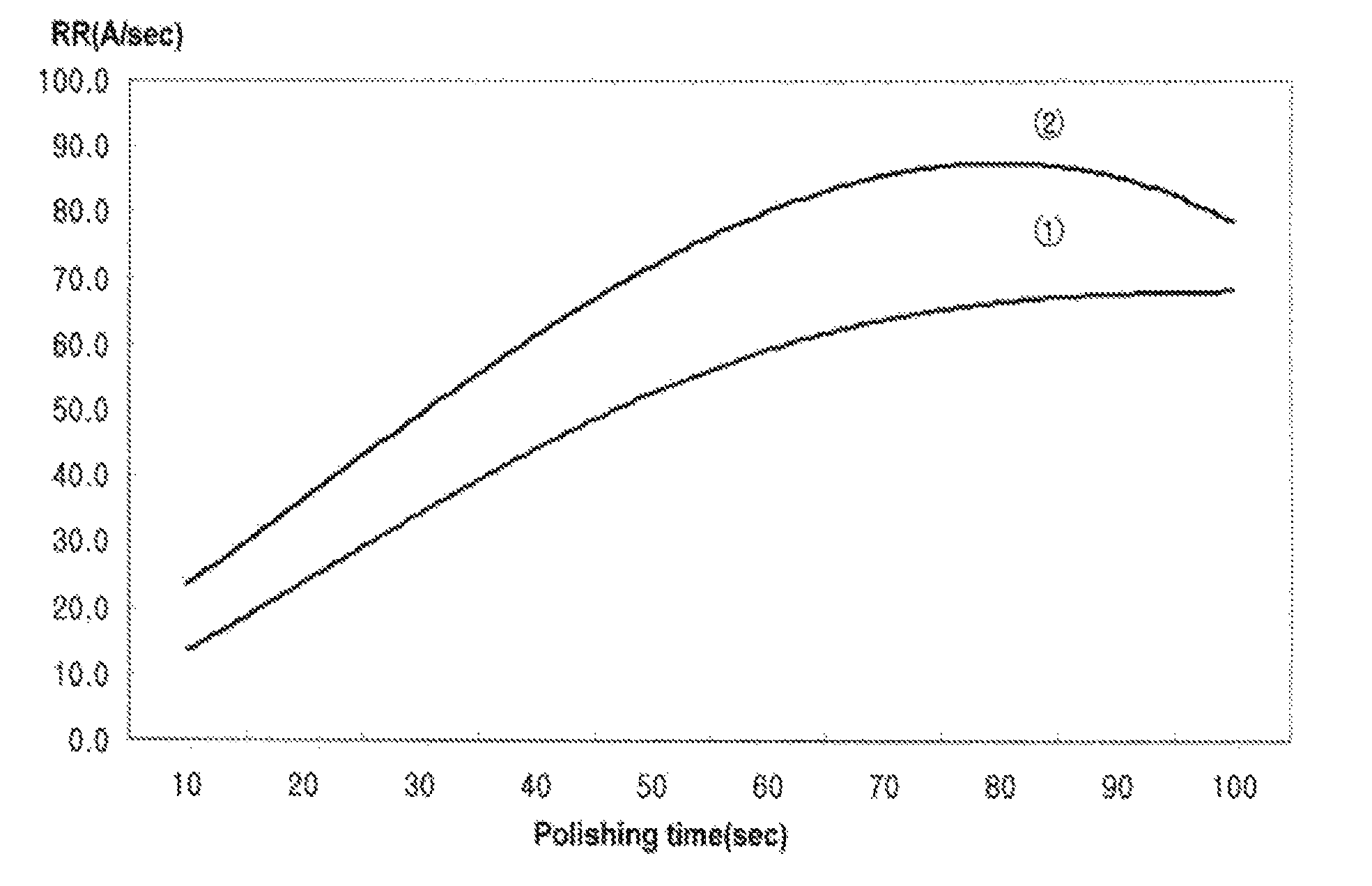
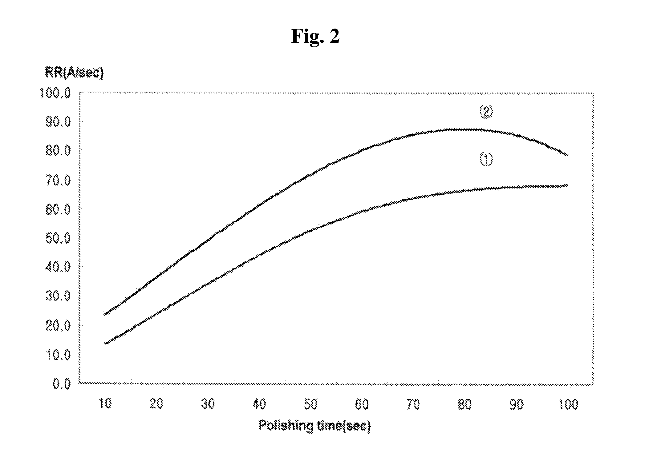
[0054]In addition, the removal rate (Å / sec) of the W film according to polishing time (sec) was measured, and the measurement results are shown in FIG. 2. In FIG. 2, “①” is remov...


PUM

PropertyMeasurementUnit
Temperatureaaaaaaaaaa
Particle sizeaaaaaaaaaa
Volumeaaaaaaaaaa

Abstract

Disclosed herein are a chemical mechanical polishing slurry composition for chemical mechanical planarization of metal layers, which comprises a non-ionized, heat-activated nano-catalyst, and a polishing method using the same. The polishing slurry composition comprises: a non-ionized, heat-activated nano-catalyst which releases electrons and holes by energy generated in a chemical mechanical polishing process; an abrasive; and an oxidizing agent. The non-ionized heat-activated nano-catalyst and the abrasive are different from each other, and the non-ionized, heat-activated nano-catalyst is preferably a semiconductor material which releases electrons and holes at a temperature of 10 to 100° C. in an aqueous solution state, more preferably a transition metal silicide selected from the group consisting of CrSi, MnSi, CoSi, ferrosilicon (FeSi), mixtures thereof, and most preferably, a semiconductor material such as nano ferrosilicon. The content of the content of the non-ionized, heat-activated nano-catalyst is 0.00001 to 0.1 wt % based on the total weight of the slurry composition.

Description

CROSS-REFERENCE TO RELATED APPLICATIONS[0001]This application claims the benefit of Korean Patent Application No. 10-2009-74344, filed On Dec. 8, 2009, which is incorporated herein by reference in its entirety.BACKGROUND OF THE INVENTION[0002](a) Field of the Invention[0003]The present invention relates to a chemical mechanical polishing slurry composition which is used in the manufacture of semiconductor chips, and more particularly to a polishing slurry composition, which comprises a non-ionized, heat-activated nano-catalyst and is particularly useful for a process for chemical mechanical planarization of a metal layer, and to a polishing method using the same.[0004](b) Background of the Related Art[0005]Semiconductor chips to which integrated circuit technology has been applied include numerous functional elements (devices), including transistors, capacitors, resistors and the like. Such individual functional elements are connected to each other by interconnects designed in speci...

Claims


Application Information

Patent Timeline
IPC IPC(8): C09K13/04
CPCH01L21/3212C09G1/02C09K3/14B24B1/00B82B3/00
Inventor PARK, JONG DAILIM, JIN HYUKCHOI, JUNG MINKONG, HYUN GOOKIMPARK, HYE JUNG
Owner DONGJIN SEMICHEM CO LTD
Why Eureka
Try Eureka