Group III nitride crystal, crystal growth process and crystal growth apparatus of group III nitride

a technology of nitride crystals and growth processes, which is applied in the direction of crystal growth process, polycrystalline material growth, condensed vapor growth, etc., can solve the problems of increased crystal defects, large operational power, and difficulty in increasing the lifetime, so as to increase the pressure of said substance containing nitrogen, increase the nitrogen concentration in the melt mixture, and easy control of the process condition

Inactive Publication Date: 2011-07-19
SUMITOMO CHEM CO LTD
View PDF19 Cites 2 Cited by
  • Summary
  • Abstract
  • Description
  • Claims
  • Application Information

AI Technical Summary

Benefits of technology

[0031]Another and more specific object of the present invention is to provide a crystal growth process and a crystal growth apparatus of a group III nitride capable of suppressing formation of the polycrystalline aggregate covering the melt mixture surface and thus capable of performing stabile crystal growth of the group III nitride.
[0095]According to the present embodiment, the melt mixture surface is no longer covered with the polycrystalline aggregate and the problem of depletion of the group III element in the melt is eliminated. Thus, it becomes possible to conduct a stable crystal growth of the group III nitride in the vicinity of the melt surface. Because of the high nitrogen concentration in the vicinity of the melt surface, it becomes possible to grow a crystal having a reduced nitrogen defect by growing the crystal in the vicinity of the melt mixture surface. Further, because of the increased nitrogen concentration, a large growth rate is achieved and a large group III nitride crystal is obtained in short time.

Problems solved by technology

In the case sapphire or SiC is used as the substrate, however, there arises problems such as increased crystal defects caused by the difference of thermal expansion coefficient or lattice constant with regard to the group III nitride.
Thus, there have been various difficulties in a light-emitting device that uses such a group III nitride crystal such as poor device characteristics, difficulty in increasing the lifetime, large operational power, and the like.
As a result, there arise problems such as increased device area and increased cost.
Also, chip separation by cleaving has been difficult in a group III nitride semiconductor device produced on a sapphire substrate, and it has been difficult to form the cavity edge surface needed in a the laser diode (LD) by conducting a cleavage process.
In this case, too, it is impossible conduct the formation of cavity edge surface and the separation of the chips process simultaneously as is practiced in a conventional LD, and problems such as complexity of the process and increased cost are not avoidable.
However, the problem of insulating nature and difficulty of cleavage process mentioned before caused by the sapphire substrate is still remaining.
Further, there arise problems which lead to cost increase such as complication of the process and warp of the substrate caused by as a result of using different materials in the case of using a sapphire substrate together with a GaN thin film.
However, there has been no report about high quality GaN substrate successfully formed to have a practical size.
However, there is a problem in such an approach that crystal growth under high temperature and high pressure is necessary while the reaction vessel enduring such a high pressure and high temperature process condition is extremely expensive.
Also, there is a problem in that the crystals grown with this method form a plate-like crystal having a C principal surface of about 1 cm diameter, while the thickness thereof is only 20-30 μm at the maximum, and the crystal easily undergoes cracking or breaking during the device production process.
However, there is a problem in this method that the size of the crystal obtained is very small, not reaching 1 mm.
When this takes place, the source material is depleted due to the consumption of the group III element in the melt mixture for the formation of the polycrystalline aggregate, and the desired large crystal is not obtained.
Thus, there has been a problem in that it not possible to grow a crystal of desired size in the vicinity of the melt mixture surface.Conventional Technology 1: Journal of Crystal Growth, vol.

Method used


Image

  • Group III nitride crystal, crystal growth process and crystal growth apparatus of group III nitride
  • Group III nitride crystal, crystal growth process and crystal growth apparatus of group III nitride
  • Group III nitride crystal, crystal growth process and crystal growth apparatus of group III nitride

Examples


fourth embodiment

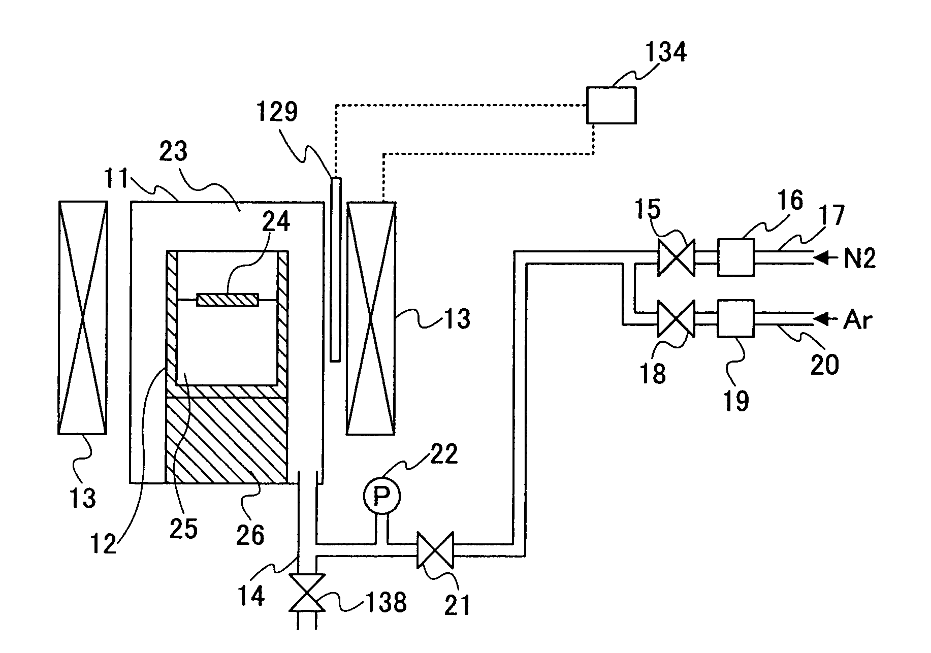
[0132]A fourth embodiment of the present invention provides a crystal growth method as set forth in the third embodiment, wherein said substance containing nitrogen is introduced into said reaction vessel after a temperature of said melt mixture has reached a specified crystal growth temperature for causing crystal growth of said group III nitride, such that the pressure of said substance containing nitrogen is increased with a controlled rate during a growth of said group III nitride.

[0133]In the conventional technologies 3, 4, 5 and 6, there has been no particular consideration with regard to the pressure increase rate of the nitrogen source gas, and because of this, numerous crystal nuclei have been formed in the melt mixture surface simultaneously, leading to formation of crystal aggregate covering the melt mixture surface. In the fourth embodiment of the present invention, on the other hand, the pressure of the substance containing nitrogen is increased gradually (slowly) so th...

fifth embodiment

[0139]A fifth embodiment of the present invention provides a crystal growth method as set forth in third embodiment, wherein said pressure of said substance containing nitrogen is held constant at the moment said group III nitride starts to crystallize.

[0140]In this fifth embodiment, the substance containing nitrogen is introduced into the reaction vessel at the temperature lower than the temperature in which the group III nitride grows, and the crystal growth is started by increasing the temperature to a predetermined crystal growth temperature while holding the pressure constant. Thereby, the pressure may be held constantly by discharges the gas to the outside of the reaction vessel by the opening or closing of the valve that divides and reaction vessel and the outside. Alternatively, there is a method of providing a tank accumulating the gas of the substance containing nitrogen outside of the reaction vessel in connection therewith such that the pressure fluctuation inside the re...

sixth embodiment

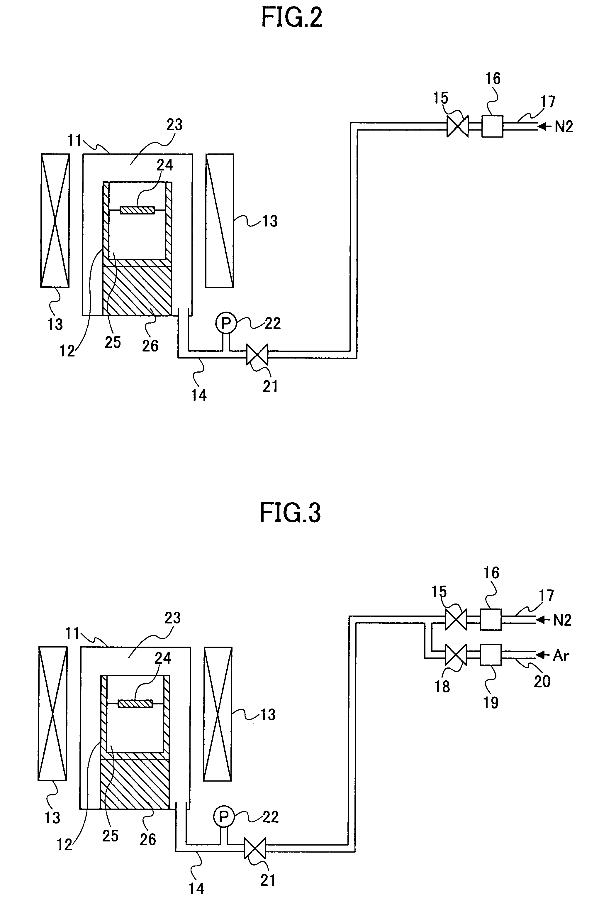
[0142]A sixth embodiment of the present invention provides a crystal growth apparatus for crystallizing a group III nitride formed of a group III element and nitrogen from a melt mixture of an alkali metal and a substance containing a group III element and a substance containing nitrogen, comprising: a reaction vessel holding therein said melt mixture; and a pressure control system keeping a pressure of said substance containing nitrogen constant.

[0143]Here, it should be noted that the mechanism for maintaining the pressure of the substance containing nitrogen is not limited the one discharging the gas to the outside by opening or closing of the valve or the one suppressing the pressure fluctuation of the gas by providing a tank accumulating the gas outside the reaction vessel. Any other suitable mechanism can be used in the present invention.


PUM

PropertyMeasurementUnit
diameteraaaaaaaaaa
diameteraaaaaaaaaa
temperatureaaaaaaaaaa

Abstract

A crystal growth method of a group III nitride includes the steps of forming a melt mixture of an alkali metal and a group III element in a reaction vessel, and growing a crystal of a group III nitride formed of the group III element and nitrogen from the melt mixture in the reaction vessel, wherein the step of growing the crystal of the group III nitride is conducted while controlling an increase rate of degree of supersaturation of a group III nitride component in the melt mixture in a surface region of the melt mixture.

Description

CROSS-REFERENCE TO RELATED APPLICATIONS[0001]This application is a divisional of U.S. patent application Ser. No. 10 / 702,776, filed on Nov. 7, 2003, now U.S. Pat. No. 7,220,311 the subject matter of which is incorporated in its entirety by reference herein.BACKGROUND OF THE INVENTION[0002]The present invention relates to a group III nitride crystal and crystal growth process and crystal growth apparatus of a group III nitride.[0003]At present, the device of InGaAlN system (group III nitride) used for purple, blue or green optical source is mostly produced by a crystal growth process such as MO-CVD process (metal-organic chemical vapor deposition process), MBE process (the molecular beam epitaxy process), and the like, conducted on a sapphire or SiC substrate. In the case sapphire or SiC is used as the substrate, however, there arises problems such as increased crystal defects caused by the difference of thermal expansion coefficient or lattice constant with regard to the group III n...

Claims


Application Information

Patent Timeline
Patent Type & Authority Patents(United States)
IPC IPC(8): C30B11/04C30B9/00
CPCC30B9/00C30B29/403C30B29/406Y10T117/1092Y10T117/1096
Inventor IWATA, HIROKAZUSARAYAMA, SEIJI
Owner SUMITOMO CHEM CO LTD
Why Eureka
Try Eureka