Airborne power station

a solar power station and airborne technology, applied in the field of solar cell array deployment, can solve the problems of low solar energy output per square meter of solar collection area, low solar energy efficiency, and low solar energy efficiency, and achieve the effects of reducing the effect of wind current, bright sunlight, and high duty cycl

Active Publication Date: 2011-08-16
THE BOEING CO
View PDF6 Cites 12 Cited by
  • Summary
  • Abstract
  • Description
  • Claims
  • Application Information

AI Technical Summary

Benefits of technology

The apparatus generally comprises an airborne platform that includes a solar power generation system in the form of a PV cell array, one or more microwave transmitters electrically connected to the solar power generation system for transmitting power to one or more microwave power receivers on the Earth's surface, a control station and a communication system linking the control station with the airborne platform. A navigation system, including a propulsion system, allows the airborne platform to maintain a position relative to the microwave receivers. The airborne platform may further be tethered to a specific location at the Earth's surface.
The airborne platform supports the solar cell array above the clouds and other atmospheric attenuation. The PV cell array may include individual steering elements or steerable solar energy collection panels that track the sun throughout the day. These steering elements may be at least partially independent of the steering of the airborne platform to minimize the effect of wind currents on the ability to maintain direct sunlight on the PV array. As a result, the solar cells have a high duty cycle, i.e., they are exposed to direct sunlight roughly 12 hou

Problems solved by technology

Concentrator PV cell systems require fewer PV cells but can only convert direct sunlight to electricity, and therefore require a tracking system and clear skies.
One drawback in the implementation of each of these systems commercially is the expense associated with producing PV cells, tracking systems, and land costs.
Moreover, solar power is not economically viable in cloudy regions such as the Northwestern United States or Northern Europe.
Though solar power technically is feasible in these regions, the long intervals of low illumination a) drive a requirement for very large energy storage systems to provide power throughout the dark intervals, b) reduce the annual energy output per square meter of solar collection area, and c) do not allow use of concentrator PV cells during the frequent intervals of thin overcast.
Another market in which solar power is not currently economically feasible is in providing power for military forces, disaster relief, or other mobile applications that require infrastructure.
Military forces typically consume large amounts of power, and they often use this power in locations where normal infrastructure either does not exist or is threatened by enemy forces.
For example, the Department of Defense (DOD) recently-estimated that the actual cost for a gallon of fuel for the US Army in some parts of Iraq is $700 due to the cost of convoy security for tanker trucks or the cost of helicopter airlift of petroleum to remote locations.
These are unsuitable for use by military forces or emergency response agencies.
Though these often are used by mobile forces, these power systems increase mobile forces' dependence on a steady supply of fuel, which comes at a great expense.
The

Method used


Image

  • Airborne power station
  • Airborne power station
  • Airborne power station

Examples


Embodiment Construction

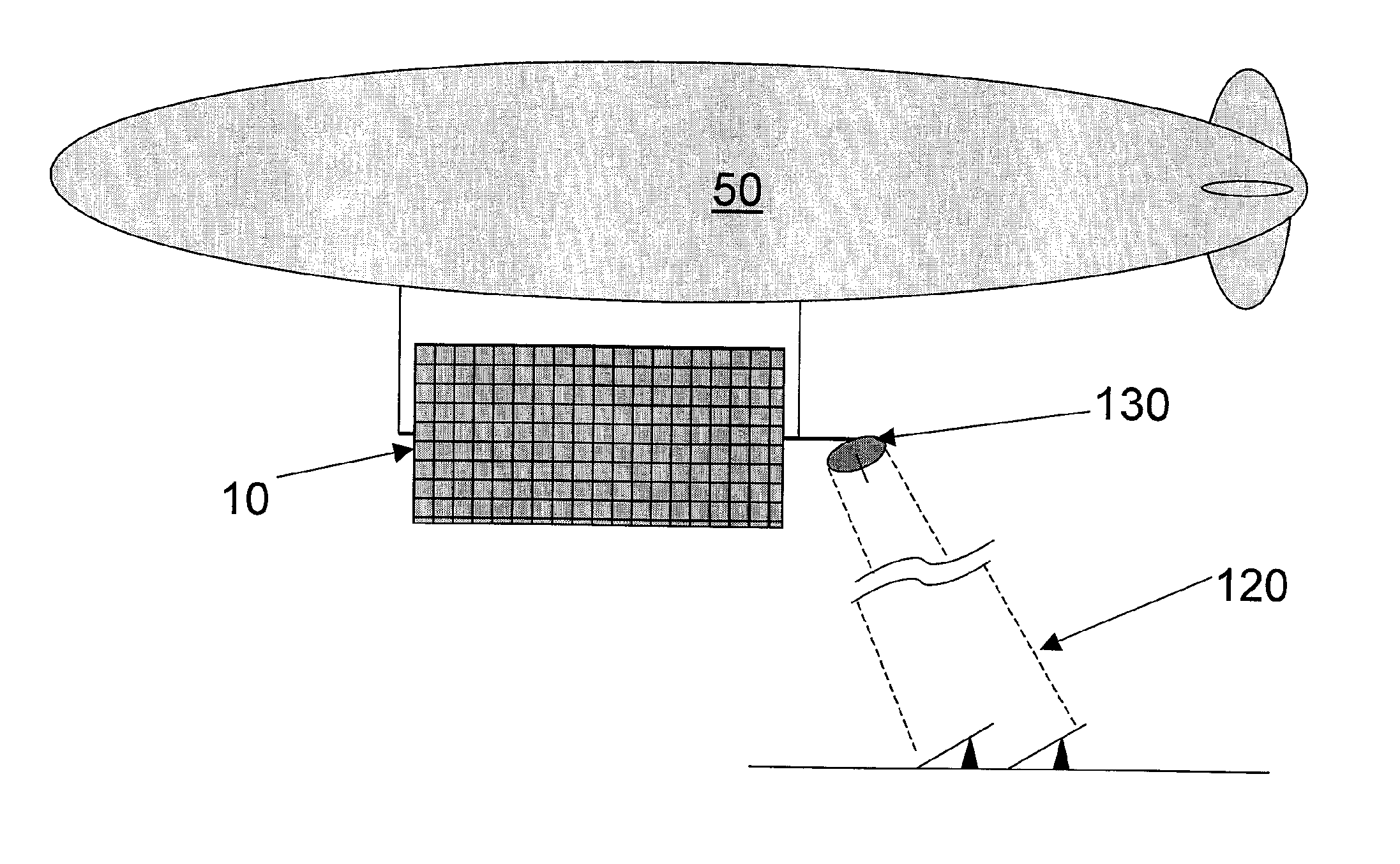
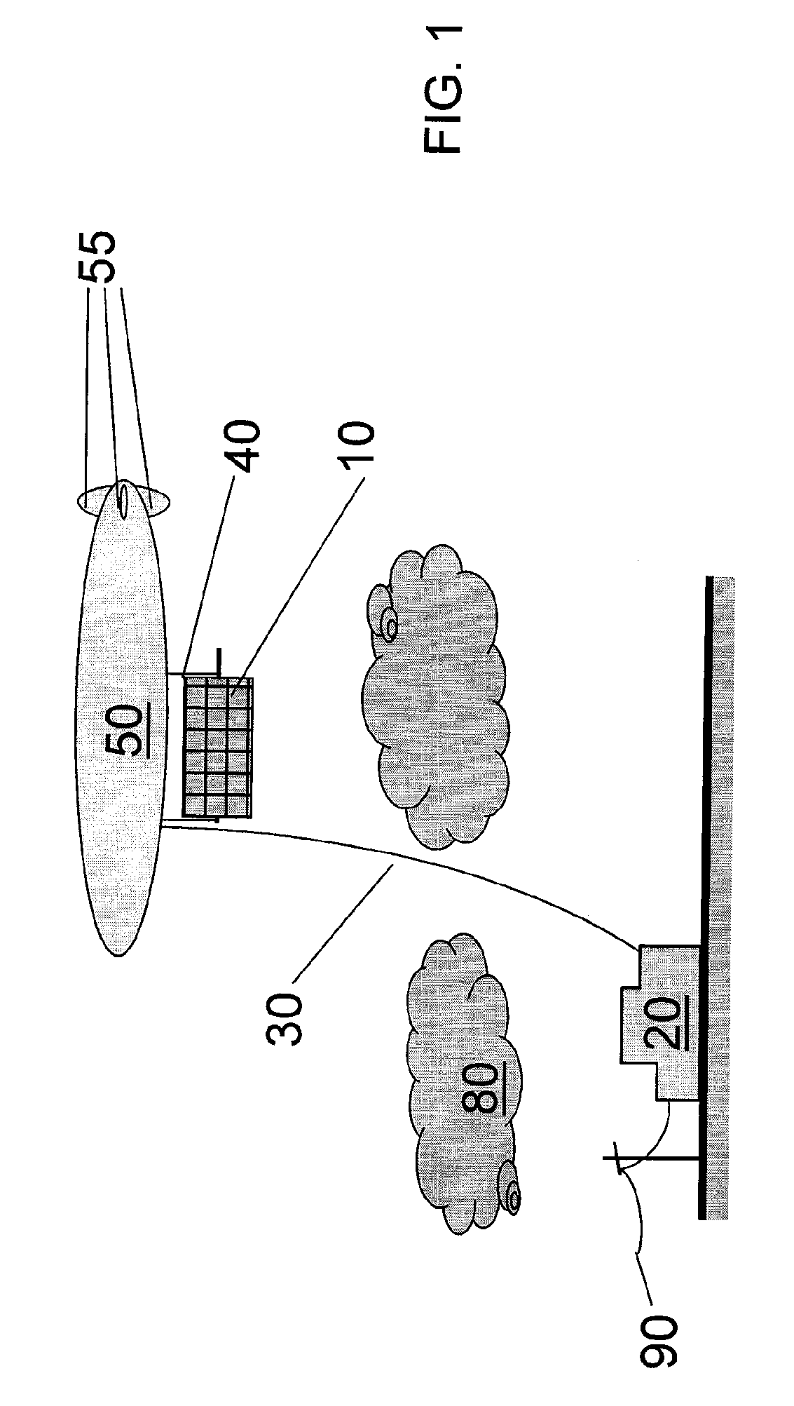
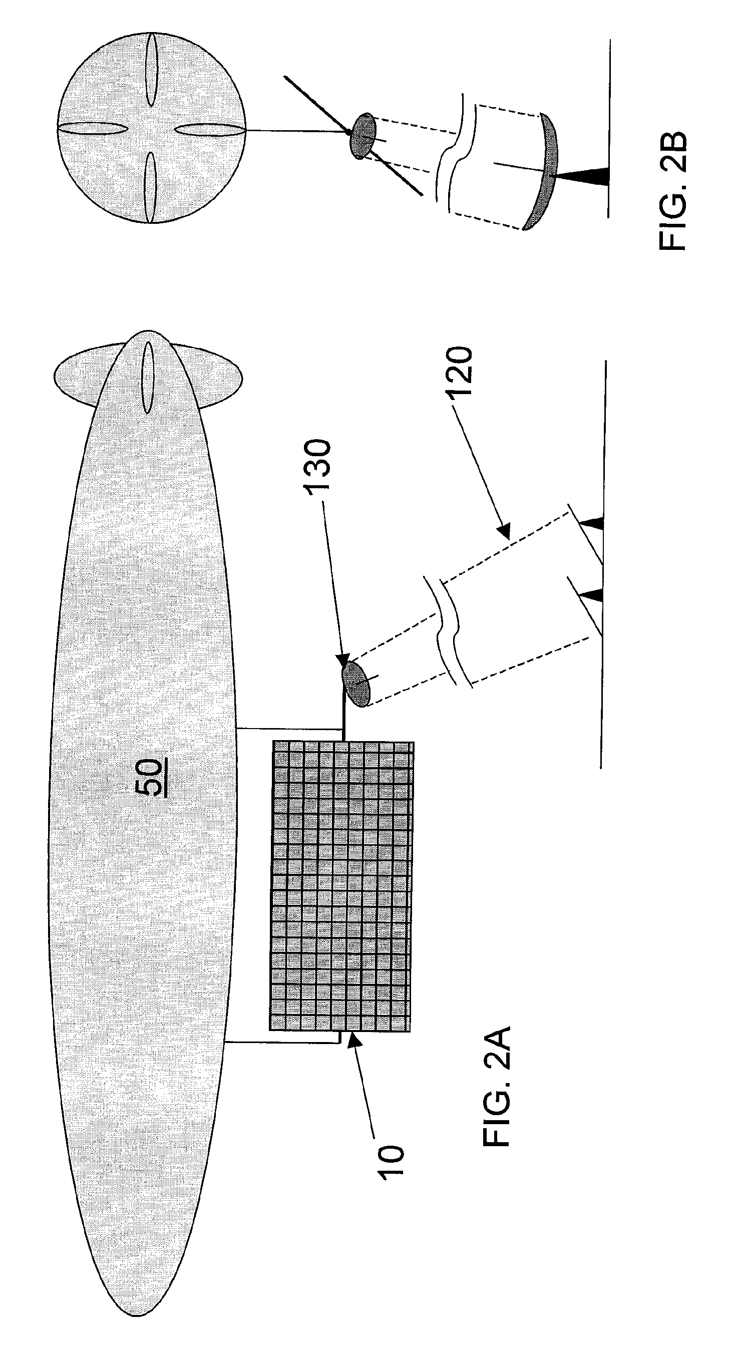
Referring to FIG. 1, in my aforesaid parent application I describe an airborne power station comprising an airborne platform 50 having a solar power generation system 10 and an electric cable 30 to transport power to the a control station 20 on the ground. The airborne platform supports the solar power generation system above the clouds 80 and other atmospheric attenuation. The control station receives the power generated at the airborne power station and distributes the power to, for example, local infrastructure 90.

The airborne platform may be an airship, including a blimp, a semi-rigid airship, or a rigid airship. As shown in FIG. 1, the airship 50 may have aerodynamic stabilizers 55 at the tail. The airborne platform preferably will include controls for the platform's yaw (steering), pitch, and / or roll. Airship embodiments may further include aerodynamic surfaces designed to produce lift when the wind blows.

The solar power generation system may be one or more photovoltaic (PV) c...


PUM


Abstract

A system for generating power from sunlight collected substantially above the earth's surface comprises an airborne platform which supports an apparatus to collect sunlight, an apparatus to convert sunlight to electricity, and an apparatus to transmit the electricity to a selected location on the earth's surface. The airborne platform collects solar energy above the clouds and transmits the energy to a receiving station on the ground via a microwave transmission system, avoiding possible attenuating effects of clouds and pollution.

Description

FIELDThe present disclosure is generally related to an apparatus and method for conversion of solar energy to electricity, more particularly, is related to the deployment of solar cell arrays for maximum utilization.BACKGROUNDThere is currently a large domestic and international market for clean non-polluting generated grid and remote electrical power, such as the electrical power generated by solar energy generating systems. This demand is anticipated only to grow.Terrestrial solar power systems typically are formed of flat panel photovoltaic (PV) cells, concentrator PV cell systems, or concentrator turbogenerators. Flat panel PV cell systems are advantageous in that they convert either direct or diffuse sunlight to electricity, though direct sunlight is preferred. The panels usually are stationary and the systems can become very large in order to generate sufficient amounts of electricity. Concentrator PV cell systems require fewer PV cells but can only convert direct sunlight to ...

Claims


Application Information

Patent Timeline
IPC IPC(8): B64B1/00B64D41/00B64B1/18
CPCF24J2/5271H02S20/00Y02E10/47Y02E10/50F24S20/80
Inventor TILLOTSON, BRIAN J.
Owner THE BOEING CO
Why Eureka
Try Eureka