Rare-earth oxyorthosilicate scintillator crystals and method of making rare-earth oxyorthosilicate scintillator crystals

a technology of rare earth oxyorthosilicate and scintillator crystals, which is applied in the direction of crystal growth process, crystal growth process, polycrystalline material growth, etc., can solve the problems of significant influence on the size and quality of grown crystals, and achieve short decay time, improved light yield and uniformity, and high light yield

Active Publication Date: 2011-11-22
SIEMENS MEDICAL SOLUTIONS USA INC
View PDF4 Cites 18 Cited by
  • Summary
  • Abstract
  • Description
  • Claims
  • Application Information

AI Technical Summary

Benefits of technology

[0005]The present disclosure relates generally to LSO scintillators with high light yield and short decay times, and method of making such scintillators. In one arrangement, the method includes codoping LSO with cerium and another dopant from the IIA or IIB group of the periodic table of elements. The doping levels are chosen to tune the decay time of scintillation pulse within a broader range (between about ˜30 ns up to about ˜50 ns) than reported in the literature, with improved light yield and uniformity, while ensuring crystal growth stability.

Problems solved by technology

The size and quality of the grown crystals can be significantly affected by the growth stability.

Method used


Image

  • Rare-earth oxyorthosilicate scintillator crystals and method of making rare-earth oxyorthosilicate scintillator crystals
  • Rare-earth oxyorthosilicate scintillator crystals and method of making rare-earth oxyorthosilicate scintillator crystals

Examples


examples 1-12

[0036]LSO scintillator crystals were grown using the well-known Czochralski process (cited above). Starting materials Lu2O3, SiO2, CeO2, ZnO, CaO, MgO, SrCO3, Y2O3 were at least 99.99% pure. Nominal concentrations of codopants in the melt were adjusted according to codoping schemes 1-3 discussed above. The actual concentration of codopants in the crystal may differ from the concentration in the melt due to the solid-liquid segregation and the fraction of the melt solidified. The crystals were grown with pull rate ˜3 mm per hour, with a rotation rate 1 rpm. The growth atmosphere composition during crystal growth and cooldown was maintained constant with approximately one percent of oxygen in bulk nitrogen. The crystals were grown to about 80 mm in diameter and about 240 mm in length. The slabs had 20 mm in thickness and were cut and numbered, starting from the bottom section of the crystal boule. Light output measurements were done under excitation with Cs137 gamma source (662 keV). ...

example 1

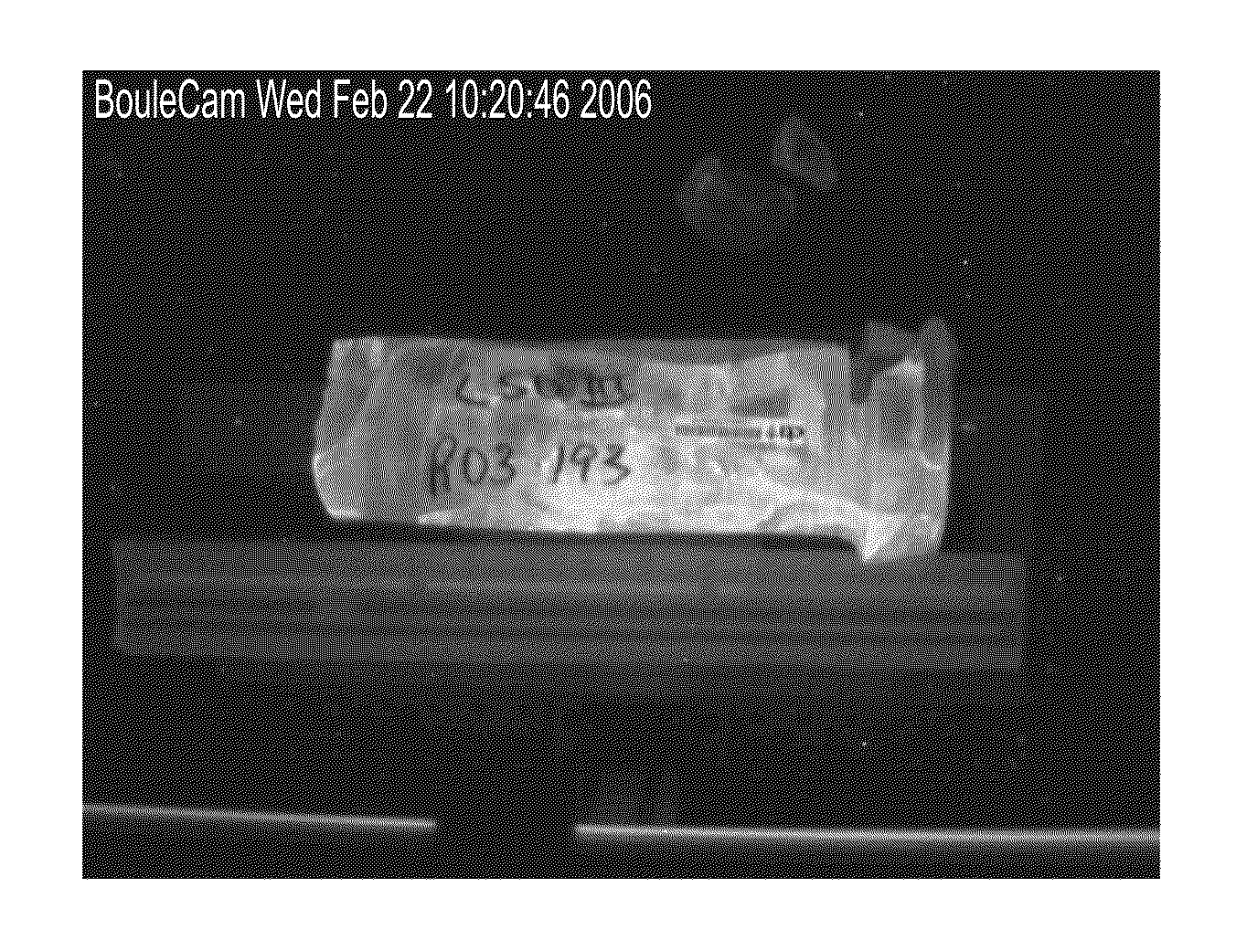
[0037]FIG. 1 shows a LSO crystal boule with high concentrations of 0.1% Ce and 0.05% Ca. Crystal growth instability problems occurred during growth process. This crystal was grown using the art of Spurrier (U.S. patent application Ser. No. 11 / 842,813) applied to a commercial size LSO boule.

example 2

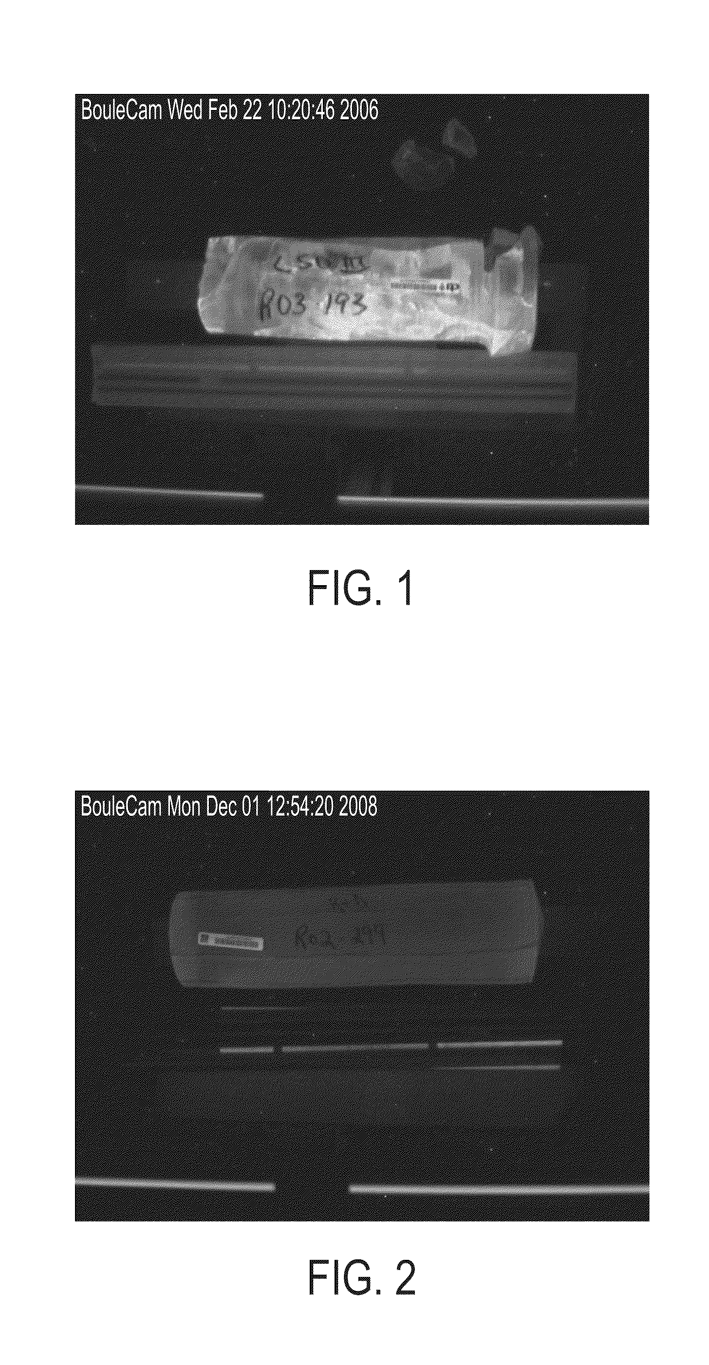
[0038]FIG. 2 shows a LSO crystal boule with Ce and Ca with appropriate adjustments of cerium and calcium concentrations according to scheme 2. The commercial size crystal boule was grown under stable growth conditions, with 0.025% Ce and 0.1% Ca, respectively.

[0039]In example 1 cerium concentration is relatively high, calcium content is a factor of 2 lower than cerium. However, a combined effect of Ce and Ca introduces instabilities in crystal-melt interface causing severe crystal cracking and loss of control over the crystal growth process. In the example 2, Ce concentration is 4 times lower, and calcium concentration is 2 times higher than in the example 1. However, combined effect of Ce and Ca does not affect crystal growth stability. Higher concentration of Ca over Ce is necessary to achieve scintillation time profile that is favorable for application in TOF PET.


PUM

PropertyMeasurementUnit
fluorescence decay timeaaaaaaaaaa
decay timeaaaaaaaaaa

Abstract

A method of making LSO scintillators with high light yield and short decay times is disclosed. In one arrangement, the method includes codoping LSO with cerium and another dopant from the IIA or IIB group of the periodic table of elements. The doping levels are chosen to tune the decay time of scintillation pulse within a broader range (between about ˜30 ns up to about ˜50 ns) than reported in the literature, with improved light yield and uniformity. In another arrangement, relative concentrations of dopants are chosen to achieve the desired light yield and decay time while ensuring crystal growth stability.

Description

TECHNICAL FIELD[0001]This disclosure relates to scintillator materials used for detecting ionizing radiation in nuclear imaging applications particularly PET (Position Emission Tomography), TOF PET (Time of Flight Positron Emission Tomography) and / or DOI PET (Depth of Interaction Positron Emission Tomography) imaging. This invention relates particularly to control of decay time, rise time and scintillation light yield of rare earth oxyorthosilicates. Specific arrangements also relate to control of decay time, rise time and scintillation light yield of rare earth oxyorthosilicates.BACKGROUND[0002]Lutetium oxyorthosilicate (LSO), or Lu2SiO5 activated with cerium (Ce3+), is a well-known crystal scintillator material and widely used for medical imaging, such as gamma-ray detection in positron emission tomography (PET) as well as other applications. Due at least partly to its relatively high light yield and short decay time, LSO is considered to be one of the most suitable materials for ...

Claims


Application Information

Patent Timeline
Patent Type & Authority Patents(United States)
IPC IPC(8): C30B29/22
CPCC30B15/04C30B29/34
Inventor ANDREACO, MARK S.SZUPRYCZYNSKI, PIOTRCAREY, A. ANDREW
Owner SIEMENS MEDICAL SOLUTIONS USA INC
Why Eureka
Try Eureka