Hybrid photonic signal processing modules

a photonic signal and module technology, applied in the field of signal processing, can solve the problems of db loss, delay module loss, and variable delay lines for radar testing

Inactive Publication Date: 2012-05-01
UNIV OF CENT FLORIDA RES FOUND INC
View PDF41 Cites 20 Cited by
  • Summary
  • Abstract
  • Description
  • Claims
  • Application Information

AI Technical Summary

Benefits of technology

[0018]A secondary objective of the present invention is to provide methods, systems, apparatus and devices for a variable optical delay line design that can realize these difficult delay line requirements.
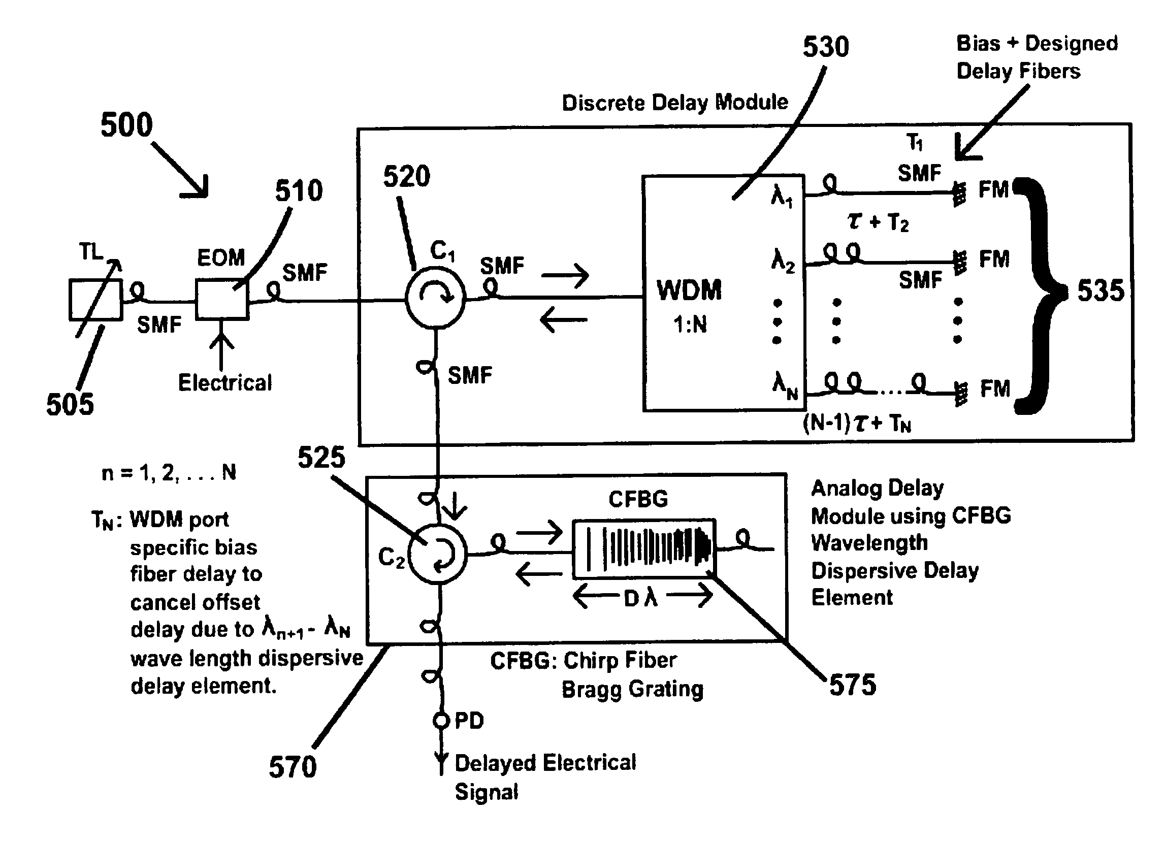
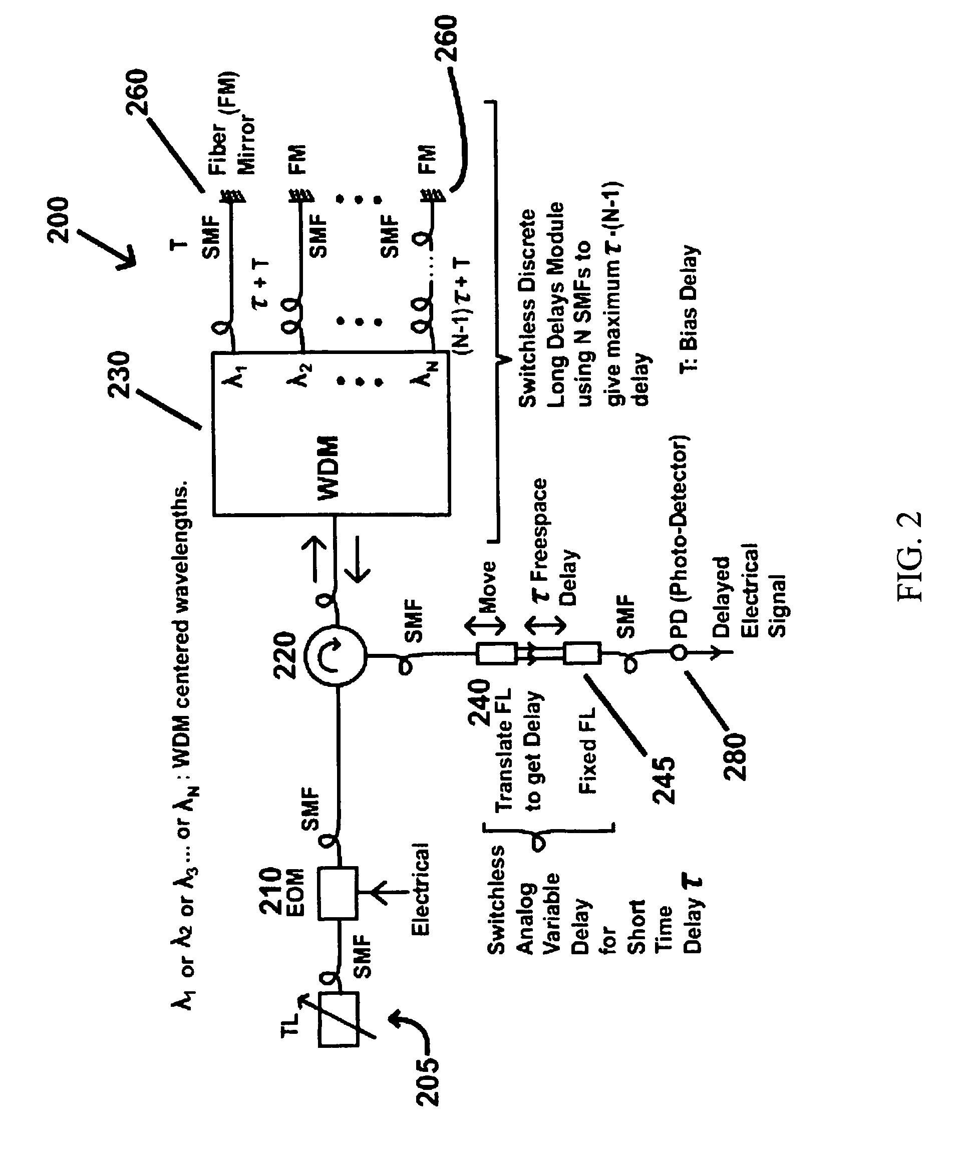
[0019]A third objective of the present invention is to provide methods, systems, apparatus and devices for a hybrid design that uses optimized laser wavelength selection / tuning in combination with spatial dispersive elements (called WDM devices) coupled with optical fibers and temporally dispersive optical delay elements such as a chirped fiber Bragg grating to generate near continuous time delays over a long time delay range.

Problems solved by technology

In addition, radar testing also requires variable delay lines.
Uses of fast optical switches in realizing digitally switched N-bit (N 6 bits) optical delay lines makes the delay module very lossy (e.g., 20 dB loss).
In effect, getting smaller resolutions across larger time delay ranges means adding more cascading, leading to higher losses and greater module complexity.
Hence a dilemma exists to get both high resolution and long time delay range while keeping loss numbers down.
Later the concept was extended to use a chirped Fiber Bragg Gratings to generate near continuous time delay for a phased array control application, but over short time delay range due to the fabrication size limitations of Fiber Bragg Gratings and the specified laser small tuning range.
187-189, 2005 that leads to 6 times reduction in fiber lengths, although at the cost of higher optical losses.
Another wavelength sensitive design for a time delay beamformer uses a single fixed CFBG but variable optical filters splits the N delayed wavelengths by a factor of N to distribute to the N-antenna elements causing an inefficient beamformer design as N scales to larger numbers.
In this case, long nanoseconds range time delays would need many km of dispersive fiber adding weight and temperature sensitivity to the variable fiber optic delay line module.
(2003 PTL paper) and B. Vidal ECOC 2002 papers also suggest slight detuning of the multiple wavelengths, with wavelength gaps equal to the arrayed waveguide grating's free spectral range to fine tune their filter, but also point out that this fine tuning is highly limited (e.g., <3% of tuning range) to a very small wavelength shift (e.g., 50 GHz) as the AWG device's passband is practically limited.

Method used


Image

  • Hybrid photonic signal processing modules
  • Hybrid photonic signal processing modules
  • Hybrid photonic signal processing modules

Examples


Embodiment Construction

[0050]Before explaining the disclosed embodiments of the present invention in detail it is to be understood that the invention is not limited in its application to the details of the particular arrangements shown since the invention is capable of other embodiments. Also, the terminology used herein is for the purpose of description and not of limitation.

[0051]The following is a list of the reference numbers used in the drawings and the detailed specification to identify components:

[0052]

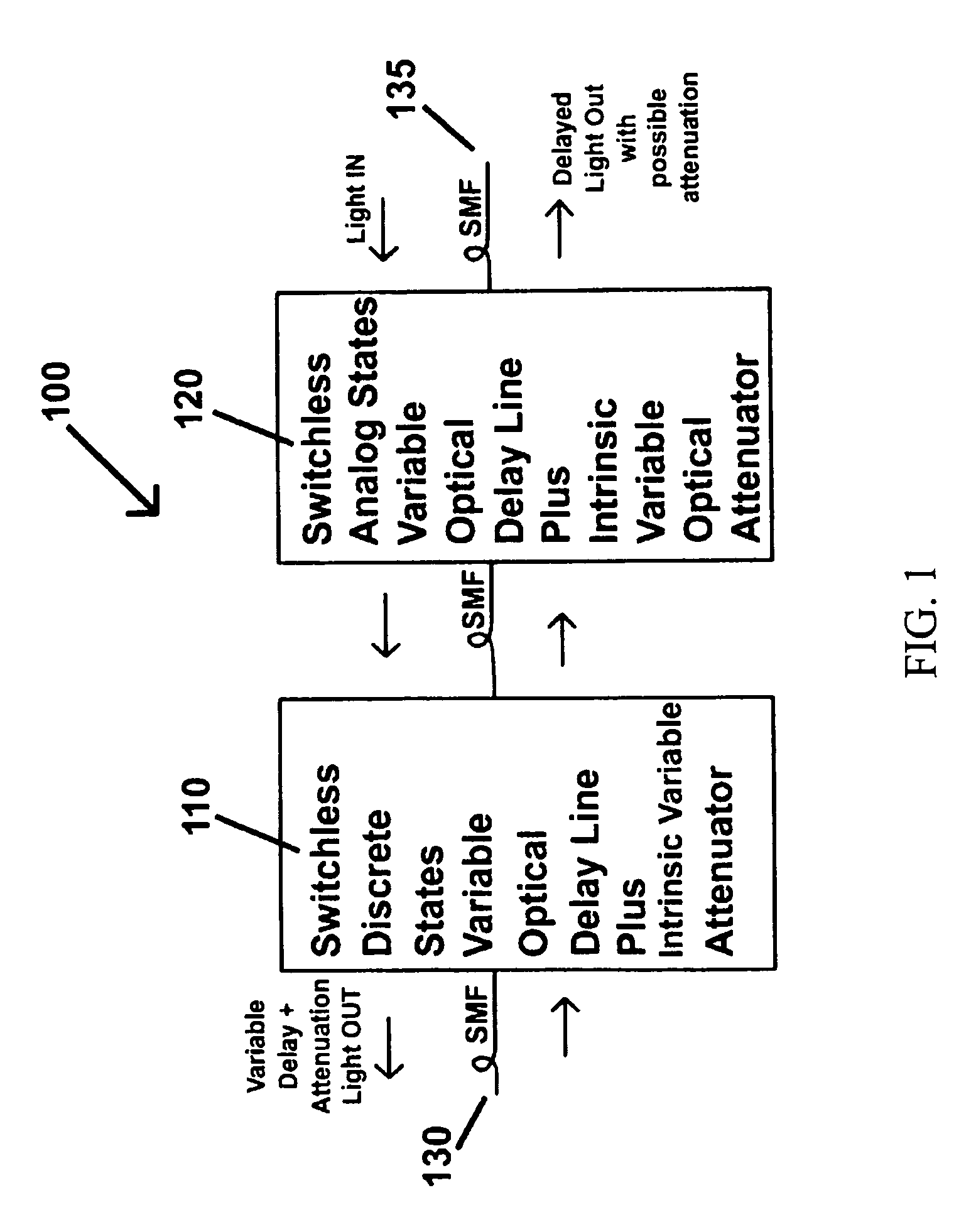
100variable fiber optic delay line110discrete delay structure120analog delay structure130input port135output port200D / A VODL205tunable laser210electro-optic modulator215single mode fiber220optical circulator230wave division multiplexing device240fiber lens245fiber lens260fiber mirrors280photo-detector300discrete state delay line & VOA305tunable lens310electro-optic modulator320circulator340fiber lens360mirror370looped fiber delay375looped fiber delay380photo detector400analog optical delay420circulat...


PUM


Abstract

Methods, systems, apparatus and devices for a variable fiber optic delay line that includes an electro-optic modulator for receiving and modulating an input signal, a switchless discrete long time delay module for injecting a long time delay into the modulated signal to produce a long delayed signal, and a switchless analog variable short delay module injecting a variable short time delay into the long delayed signal for a delayed output signal having a delay approximately equal to the long plus the short time delay. The module may also include non-dispersive single mode fibers for transmission between components and a circulator coupled for routing the input signal to the discrete long time delay module and routing the first delayed output signal to the analog variable short delay module. The VFODL can be used for Radio Frequency, digital electrical signals requiring time delay and amplitude processing or optical signal processing.

Description

[0001]This application claims the benefit of priority to U.S. Provisional application No. 61 / 068,789 filed on Mar. 10, 2008.FIELD OF INVENTION[0002]This invention relates to signal processing and, in particular, to methods, systems, apparatus and devices for hybrid analog-digital control variable optical delay lines using optimized laser wavelength selection / tuning in combination with spatial dispersive elements coup led with optical fibers and temporally dispersive optical delay elements to generate near continuous time delays over a long time delay range.BACKGROUND AND PRIOR ART[0003]Search and tracking of fast moving objects requires fast moving high spatial resolution radar beams. To achieve this goal, phased array antennas / radars operate with wide instantaneous bandwidths that requires true time delay radar beamforming implemented with variable delay lines. In addition, radar testing also requires variable delay lines. Radar systems operate over varied radar bands from S-band t...

Claims


Application Information

Patent Timeline
Patent Type & Authority Patents(United States)
IPC IPC(8): G02B6/26G02B6/42
CPCG02B6/2861H04J14/02G02B6/12019G02B6/29316G02B6/3516G02B17/023
Inventor RIZA, NABEEL A.
Owner UNIV OF CENT FLORIDA RES FOUND INC
Why Eureka
Try Eureka