
Electrochemical device

a technology of electrochemical device and polymer electrolyte, which is applied in the direction of electrochemical generator, cell component details, cell components, etc., can solve the problems of low material cost, low stack output, and low stack efficiency, and achieves simple cathode current collector attachment and easy attachment to the support.

Active Publication Date: 2012-05-08
FUEL CELL TECH SWEDEN AB
View PDF20 Cites 11 Cited by
  • Summary
  • Abstract
  • Description
  • Claims
  • Application Information

AI Technical Summary

Benefits of technology

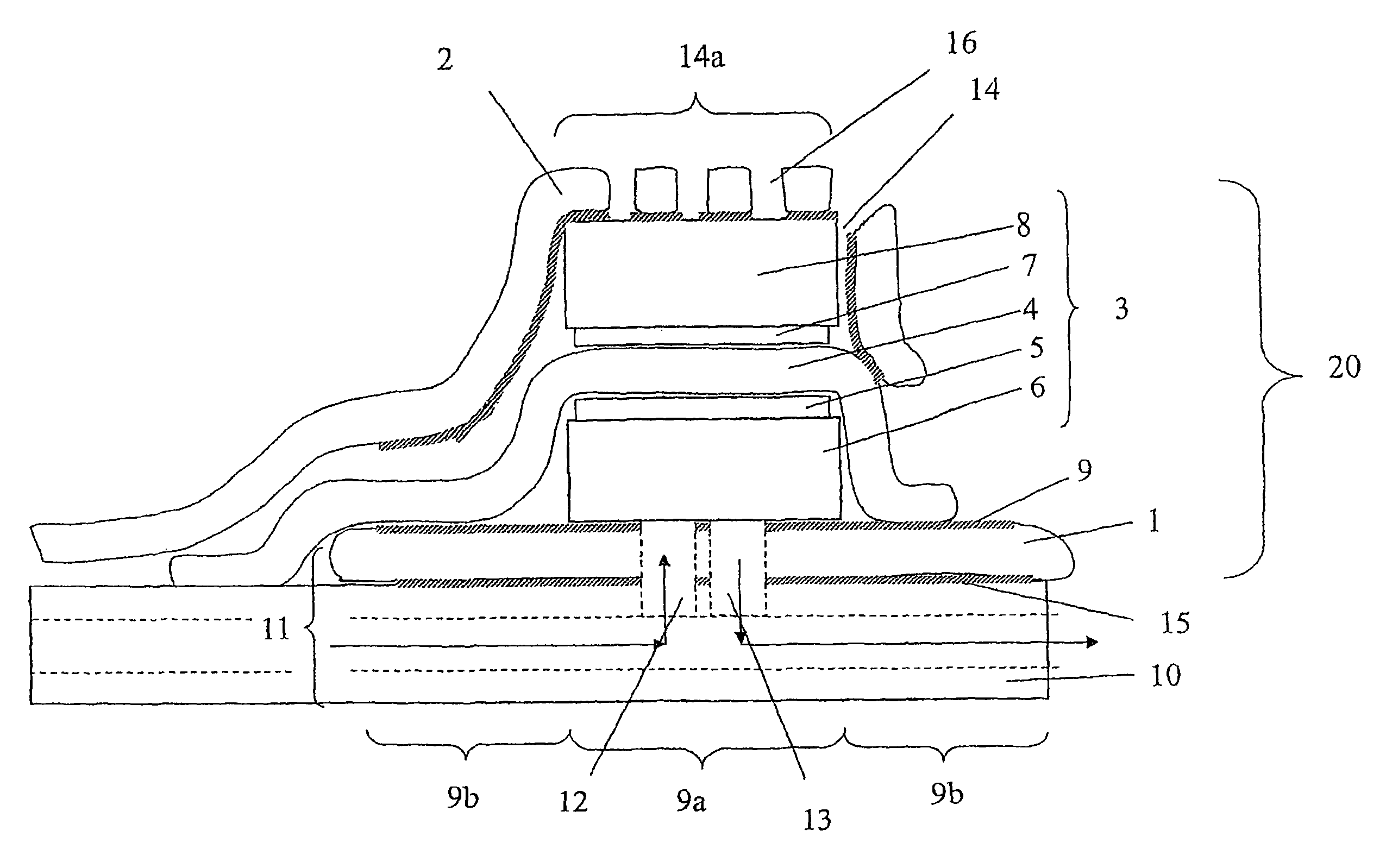
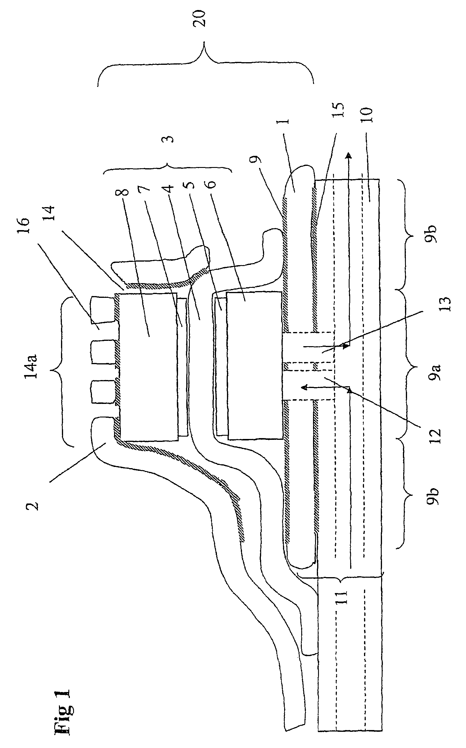
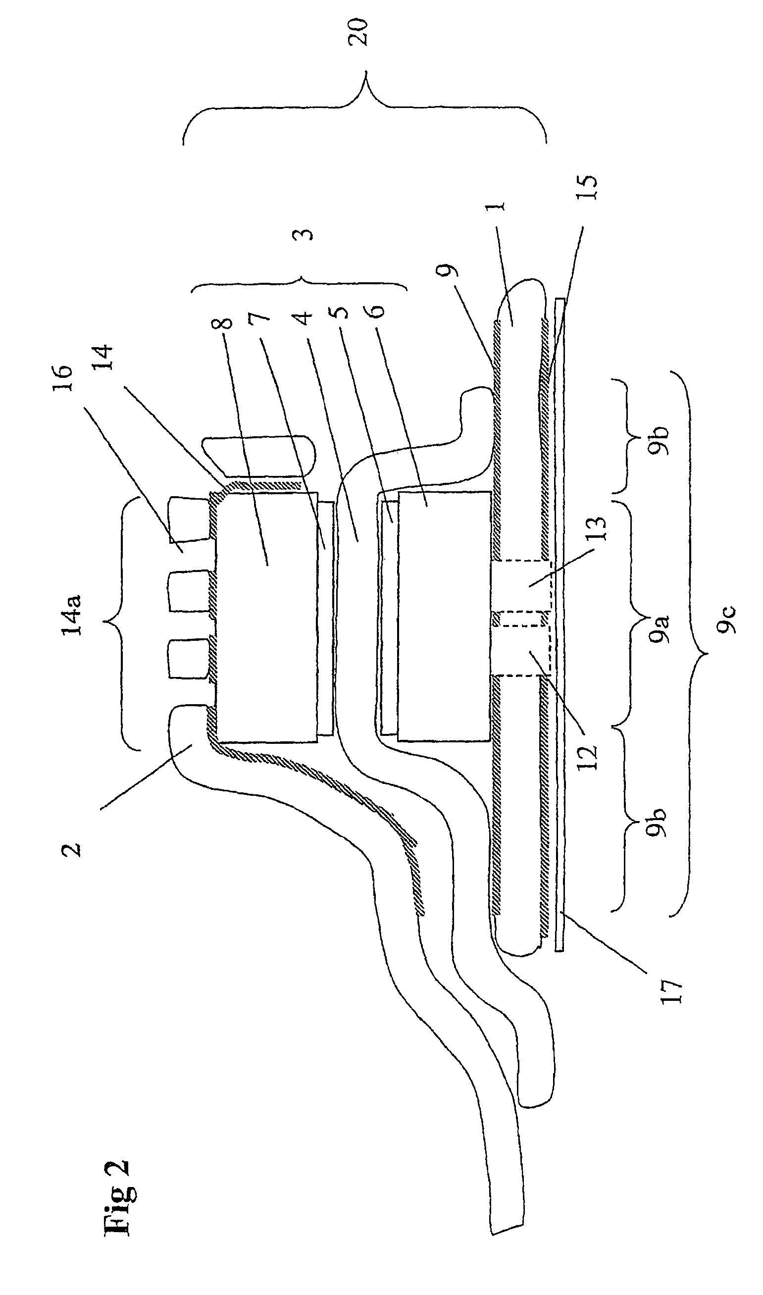
"The present invention relates to a polymer electrolyte electrochemical device, such as a fuel cell or electrolyzer, that uses an ion conducting polymer membrane electrolyte. The device includes an anode current collector, a membrane electrode assembly, and a cathode current collector. The membrane electrode assembly is sealed and attached to the anode current collector and the cathode current collector, creating an anode gas chamber. The adhesive used to attach the membrane electrode assembly to the current collectors is electrically conductive in at least one region, allowing for easy assembly of the device without the need for clamping equipment. The invention also includes components for use in a planar configuration air breathing polymer electrolyte electrochemical device. The technical effects of the invention include simplified assembly of the device and improved performance."

Problems solved by technology

Also, materials cost is a lesser barrier than in transportation applications since batteries are relatively expensive.
However, these systems are not well suited for stack outputs in the tens or hundreds of watts, since the rotating components, such as pumps and compressors, do not scale down well.
As a result even small scale systems of this design are too heavy for many small applications, such as for portable applications and personal use.
Moreover, cell stack produced by this method will still need a clamping force, especially for larger cells.

Method used


Image

  • Electrochemical device
  • Electrochemical device
  • Electrochemical device

Examples


example 1

[0051]FIGS. 5 and 6 show results for a single cell with the cathode current collector being a gold plated stainless steel net (15×15 mm). The clamping means (and current collector) was cut out from a plain Printed Circuit Board (PCB). The PCB was a commercial epoxy-glass composite uniformly plated with a 30 μm thick copper layer on one side. The Membrane Electrode Assemblies (MEAs) were Primea 5510 from Gore (0.3 mg Pt cm−2, 25 μm thick membrane). Gas backings were Carbel products from Gore, with their hydrophobic side turned against the MEA. The anode current collector was made of a copper foil having an electron-conductive adhesive film on one side. The supplier was TESA (product No. 4384). The adhesive was based on a silver-filled acrylic substance. The thickness of the adhesive film and copper foil was about 5 and 70 μm, respectively. The anode current collector was supported by the cell house, a 5 mm-thick Plexiglas sheet wherein gas channels were milled. The arrangement of the...

example 2

No Clamping Force

[0054]In another example a cell was assembled and tested where no clamping force was applied. The components were similar to what had been used in the previously mentioned cells except for the cathode current collector steel net and the PCB board. Instead as a cathode current collector a perforated conductive tape (a copper foil having an electron-conductive adhesive film on one side) was used. Before assembling the cell the MEA and the gas backings were integrated with each other into one unit by hot pressing at 110° C. The integrated gas backing and MEA was attached and sealed to the anode current collector. The MEA was made so large so that a good seal was formed and so that the anode and cathode current collectors did not short cut with each other. Finally, the cathode current collector conductive tape was connected to the cathode gas backing. The active cell area was about 2 cm2. During electrochemical cell testing with pure hydrogen it provided 500 mA at a cel...

example 3

[0055]In this example the cell area and the current collector materials were the same as in example 2. The electrodes were ELAT-electrodes (ETEK), which includes both a gas backing layer and an electrochemically active layer, with a Platinum loading of 0.5 mg / cm2. The membrane was Nafion 1035 Dupont). The membrane electrode assembly was formed by hot pressing at 110° C. Prior to hot pressing the membrane was pre-treated by boiling in 3% H2O2 for 1 hour, boiling in H2SO4 for 1 hour, and finally, two times boiling in pure H2O for 1 hour. The electrochemical testing was conducted with pure hydrogen and the results are given in Table 1.

[0056]

TABLE 1E (mV)I (mA)820060013500203503319044


PUM

PropertyMeasurementUnit
poweraaaaaaaaaa
current densitiesaaaaaaaaaa
thickaaaaaaaaaa

Abstract

A polymer electrolyte electrochemical device includes an anode current collector (1), a membrane electrode assembly (2) with anode and cathode gas backings (3, 4), and a cathode current collector (5), wherein the membrane electrode assembly is sealed and attached at least to the anode current collector by adhesive elements, thereby creating an anode gas chamber, and optionally attached to the cathode current collector by adhesive elements, the adhesive elements being electrically conducting or electrically non-conducting. The invention also relates to polymer electrolyte electrochemical device components adapted for use in a single cell electrochemical device and a series arrangement electrochemical device.

Description

TECHNICAL FIELD[0001]The present invention relates to a polymer electrolyte electrochemical device and to electrochemical device components for use in a planar configuration air breathing polymer electrolyte electrochemical devices. The electrochemical device may be use as a fuel cell or an electrolyser.BACKGROUND[0002]Generally, a fuel cell is a device which converts the energy of a chemical reaction into electricity. Fuel cells differ from batteries in that fuel and oxidant are stored external to the cell, which can generate power as long as the fuel and oxidant are supplied. A fuel cell produces an electromotive force by bringing the fuel and oxidant in contact with two suitable electrodes separated by an electrolyte. An electrolyser is a device with the opposite function of a fuel cell. It converts electrical energy to chemical energy in the form of hydrogen and oxygen. In a polymer electrolyte fuel cell, a fuel such as hydrogen gas, is introduced at one electrode where it disso...

Claims


Application Information

Patent Timeline
Patent Type & Authority Patents(United States)
IPC IPC(8): H01M2/08H01M4/02H01M8/00H01M4/64C25B9/23H01MH01M8/02H01M8/10
CPCC25B9/10H01M8/0247H01M8/0271H01M8/1002H01M8/241H01M8/0297Y02E60/521H01M8/1007C25B9/23H01M8/2418Y02E60/50H01M8/02H01M4/86
Inventor LUNDBLAD, ANDERSJAOUEN, FREDERICHAASL, SJOERDVAN DER WIJNGAART, WOUTER
Owner FUEL CELL TECH SWEDEN AB
Learn More