
Processes for converting gaseous alkanes to liquid hydrocarbons

a technology of gaseous alkanes and liquid hydrocarbons, which is applied in the field of process of converting lower molecular weight alkanes to olefins and higher molecular weight hydrocarbons, can solve the problems of high cost of lng process, limited distance over which natural gas may be transported, and high cost of gaseous transportation

Active Publication Date: 2012-05-08
SULZER MANAGEMENT AG
View PDF869 Cites 13 Cited by
  • Summary
  • Abstract
  • Description
  • Claims
  • Application Information

AI Technical Summary

Benefits of technology

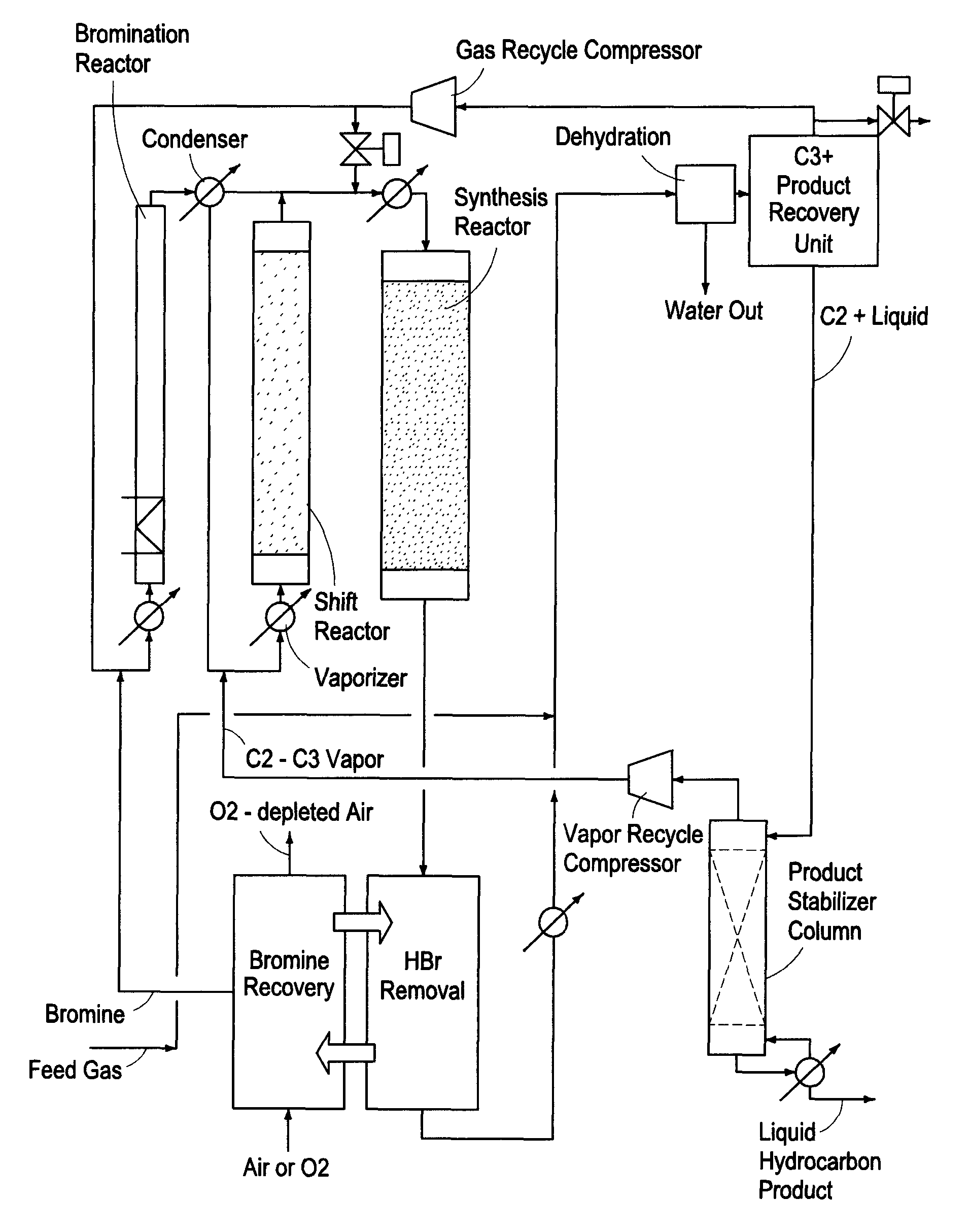
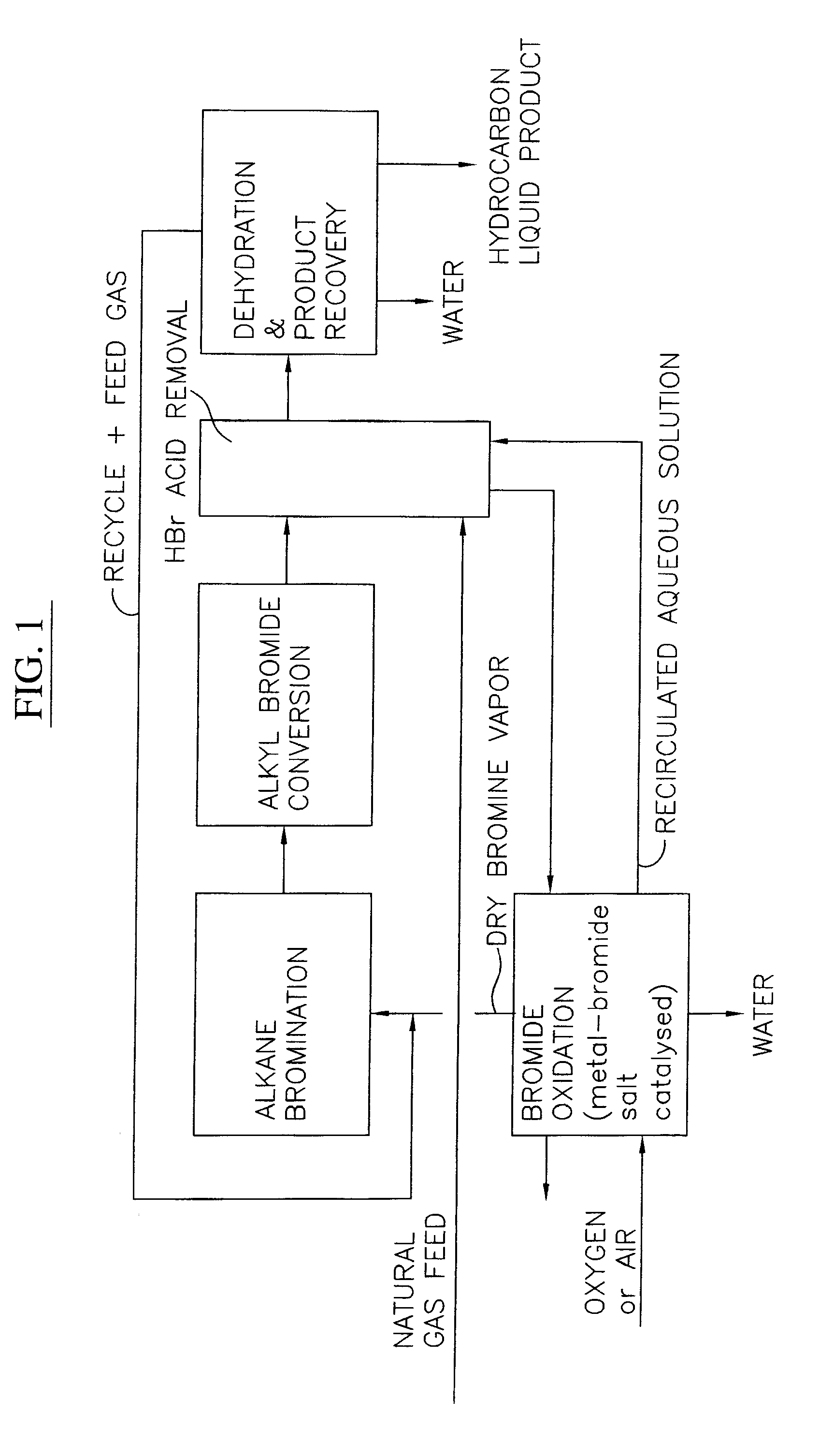
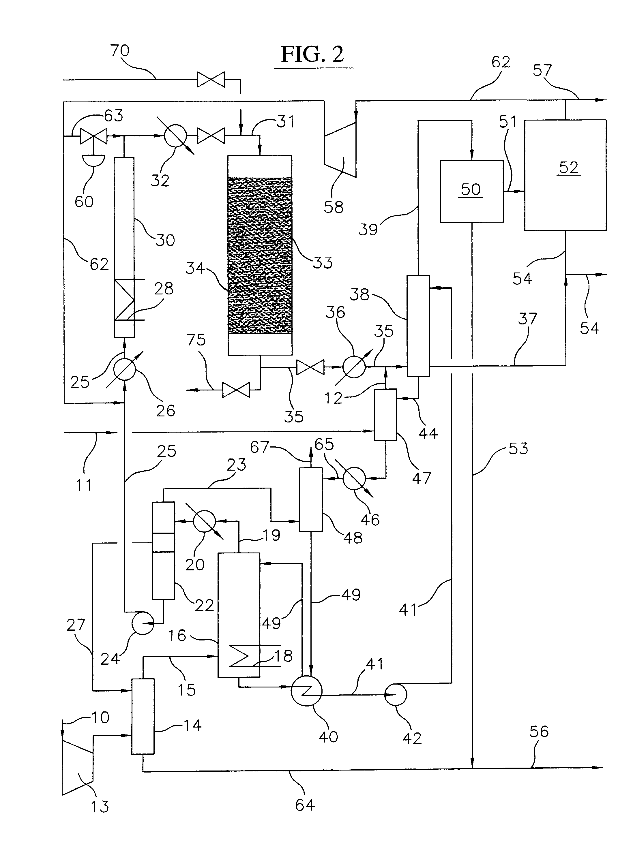
The present invention is a process where bromine is reacted with gaseous alkanes containing methane to form bromination products. These products are then reacted with a portion of the methane in the presence of a catalyst to convert poly-brominated alkanes to mono-brominated alkanes. The technical effect of this process is the improved efficiency and selectivity in the production of mono-brominated alkanes.

Problems solved by technology

Due to the low density of natural gas, transportation thereof in gaseous form, for example, by pipeline or as compressed gas in vessels, is expensive.
Accordingly, practical and economic limits exist to the distance over which natural gas may be transported in its gaseous form.
However, this LNG process is expensive and there are limited regasification facilities in only a few countries that are equipped to import LNG.
For instance, SMR and GHR usually operate at high pressures and temperatures, generally in excess of 600° C., and are endothermic reactions thus requiring expensive furnaces or reactors containing special heat and corrosion-resistant alloy heat-transfer tubes filled with expensive reforming catalyst and high-temperature heat supplied from a source external to the reactor, such as from the combustion of natural gas, as is often utilized in SMR.
POX and ATR processes usually operate at high pressures and even higher temperatures, generally in excess of 1000° C. and utilize exothermic reactions in which a significant fraction of the hydrocarbon feed is converted to CO2 and a large amount of high-temperature waste-heat must be rejected or recovered, thus complex and costly refractory-lined reactors and high-pressure waste-heat boilers to quench and cool the synthesis gas effluent are required.
Also, significant capital cost and large amounts of power are required for compression of oxygen or air to these high-pressure processes.
Thus, due to the high temperatures and pressures involved, synthesis gas technology is generally viewed as expensive, resulting in a high cost methanol product.
This cost can limit higher-value uses of the methanol, such as for chemical feedstocks and solvents.
Furthermore, it is generally thought that production of synthesis gas can be thermodynamically and chemically inefficient, in that it can produce large excesses of waste heat and unwanted carbon dioxide, which lowers the carbon conversion efficiency of the process.
Fischer-Tropsch Gas-to-Liquids (GTL) technology can also be used to convert synthesis gas to heavier liquid hydrocarbons, however investment cost for this process at this point in time are higher than other types of processes.
In each case, the production of synthesis gas represents a large fraction of the capital costs for these methane conversion processes and limits the maximum carbon efficiencies that these processes can attain.
However, to date, none of these alternatives has attained commercial status for various reasons.
Halogenation of methane using chlorine as the halogen usually results in poor selectivity to the monomethyl halide (CH3Cl), but rather produces unwanted by-products such as CH2Cl2 and CHCl3.
These are thought to be difficult to convert or require severe limitation of conversion per pass, and hence very high recycle rate.
While certain ethers, such as dimethylether (DME) are a promising potential diesel engine fuel substitute, as of yet, there currently exists no substantial market for DME, and hence an expensive additional catalytic process conversion step would be required to convert DME into a currently marketable product.
However, none of these earlier alternative approaches have resulted in commercial processes.
However due to the high cost of methanol production, and at current or projected prices for gasoline, the MTG process is not considered economically viable.

Method used


Image

  • Processes for converting gaseous alkanes to liquid hydrocarbons
  • Processes for converting gaseous alkanes to liquid hydrocarbons
  • Processes for converting gaseous alkanes to liquid hydrocarbons

Examples


example 1

[0145]A mixture of methane and vaporized bromine at various mixture ratios is flowed vertically upward through a un-packed tubular reactor which is externally heated in three zones using electrical heating elements. The top (outlet) zone is maintained at an average temperature of about 494° C., the middle zone is maintained at an average temperature of about 450° C. and the inlet (preheat) zone is operated at various temperatures over the range of about 150° C. to about 300° C. Reaction residence times ranged from about 2.0 to 4.5 seconds. As depicted in FIG. 14, increasing the molar ratio of methane to bromine introduced into the bromination reactor above 2.5 results in a significant increase in monobromination selectivity of approximately 70%. At molar ratios of methane to bromine of about 5, monobromination selectivity averages about 80%, while at molar ratios of methane to bromine of about 10, monobromination selectivity exceeds 80%. As further depicted in FIG. 15, this increase...

example 2

[0146]An externally heated open-tube (nominal ⅜-inch diameter) laboratory-scale thermal bromination reactor (R-1a) is operated upstream in series with a nominal 1-inch diameter catalytic shift reactor (R-1b) operating at about 490° C. and a GHSV of about 650° hr−1, according to the invention. Flows of methane, bromine and nitrogen are controlled to target feed CH4:Br2 ratios of either 3:1 or 2:1 to the first open-tube thermal bromination reactor. For each of the two targeted CH4:Br2 feed ratio mixtures the first open tubular thermal bromination reactor is heated (with a three-zone temperature profile from the bottom inlet to the top outlet at 425° C., 450° C. and 470° C.) to initiate the thermal gas-phase free-radical bromination reaction in the open tube thermal reactor. The compositions of samples of the inlet and outlet gases to the Catalytic Shift Reactor are shown in the table below for the two different target methane-bromine mixtures. When the thermal bromination is initiated...

example 3

[0149]An externally heated laboratory-scale catalytic shift reactor (nominal 1-inch diameter) is operated at about 490° C. and a GHSV of about 650 hr−1, according to the invention. Flows of methane, bromine and nitrogen are controlled to target feed CH4:Br2 ratios of 3:1 and are preheated to about 175° C. in the first open tube thermal bromination reactor (R-1a) and fed to the catalytic shift reactor (R-1b).

[0150]The catalyst was initially composed of a mixture of iron oxide and molybdenum oxide dispersed on a silica support, prepared using a wet precursor impregnation / post calcination method. Prior to each test the catalyst is maintained at a temperature of about 490° C. and calcinated / regenerated with a mixture of oxygen and nitrogen for several hours to insure that the catalyst was in an initial oxide form, then purged with N2, prior to the introduction of the methane-bromine reactants. As illustrated in FIG. 20, the amount of CH3Br (MeBr) increases with time for approximately th...


PUM

PropertyMeasurementUnit
temperatureaaaaaaaaaa

Abstract

A process for converting gaseous alkanes to olefins, higher molecular weight hydrocarbons or mixtures thereof wherein a gaseous feed containing alkanes is thermally reacted with a dry bromine vapor to form alkyl bromides and hydrogen bromide. Poly-brominated alkanes present in the alkyl bromides are further reacted with methane over a suitable catalyst to form mono-brominated species. The mixture of alkyl bromides and hydrogen bromide is then reacted over a suitable catalyst at a temperature sufficient to form olefins, higher molecular weight hydrocarbons or mixtures thereof and hydrogen bromide. Various methods are disclosed to remove the hydrogen bromide from the higher molecular weight hydrocarbons, to generate bromine from the hydrogen bromide for use in the process, and to selectively form mono-brominated alkanes in the bromination step.

Description

REFERENCE TO RELATED PATENT APPLICATION[0001]This application is a continuation-in-part of Ser. No. 12 / 138,877, filed Jun. 13, 2008, now U.S. Pat. No. 7,674,941 issued on Mar. 9, 2010 and entitled “Processes for Converting Gaseous Alkanes to Liquid Hydrocarbons”, which is a continuation-in-part of Ser. No. 12 / 112,926, filed Apr. 30, 2008, now U.S. Pat. No. 8,008,535 issued on Aug. 30, 2011 and entitled “Process for Converting Gaseous Alkanes to Olefins” which is a continuation of U.S. patent application Ser. No. 11 / 254,438 filed on Oct. 19, 2005 now abandoned and entitled “Process for Converting Gaseous Alkanes to Olefins and Liquid Hydrocarbons,” which is a continuation-in-part of Ser. No. 11 / 101,886, filed Apr. 8, 2005, now U.S. Pat. No. 7,348,464 issued on Mar. 25, 2008 and entitled “Process for Converting Gaseous Alkanes to Liquid Hydrocarbons,” which is a continuation-in-part of Ser. No. 10 / 826,885, filed Apr. 16, 2004, now U.S. Pat. No. 7,244,867 issued on Jul. 17, 2007 and en...

Claims


Application Information

Patent Timeline
Patent Type & Authority Patents(United States)
IPC IPC(8): C07C1/00
CPCC01B7/093C01B7/096C01B9/04C07C17/10C07C17/23C07C17/37C07C19/075C10G50/00C10L3/10C10L3/102C10G2400/20C10G2400/22C10G2300/1011C10G2300/1025Y02P30/40C07C17/013C07C17/25B01J23/42
Inventor WAYCUILIS, JOHN J.TURNER, WILLIAM J.THOMAS, RAPHAEL
Owner SULZER MANAGEMENT AG
Learn More