Systems, apparatus and methods for optimizing the production of energy products from biomass, such as sawmill waste

a technology of energy products and equipment, applied in the field of systems, apparatus and methods for the production of energy products from carbonizable materials, can solve the problems of nuclear power raising the specter of ecological damage, excessive emission of carbon dioxide into the atmosphere, and substantial environmental problems in the united states, and achieves convenient transportation, efficient pyrolysis, and high efficiency. the effect of speed

Active Publication Date: 2012-06-26
AMERICAN BIO ENERGY CONVERTING
View PDF23 Cites 10 Cited by
  • Summary
  • Abstract
  • Description
  • Claims
  • Application Information

AI Technical Summary

Benefits of technology

[0020]In some embodiments, a cyclone separator is used to separate entrained char from the exhaust. Also used in some embodiments is a biomass feed bin for introduction of biomass into the pyrolysis unit. Exhaust separated from its bio-oil vapor and char is passed through the biomass feed bin whereupon the biomass acts as a filter, cleaning remaining entrained matter from the exhaust. Also in some embodiments, char separated from the exhaust is introduced back into the pyrolysis unit to aid in producing the generally-deoxygenated heated gas stream. In yet another embodiment, the exhaust from a gas turbine is used as a heat source to promote an efficient fast pyrolysis.
[0021]The tech

Problems solved by technology

Today, the United States faces substantial environmental issues from continuing reliance on polluting energy sources such as coal, natural gas, nuclear power and hydroelectric power.
The burning of fossil fuels, such as coal and natural gas, results in the emission of excessive amounts of carbon dioxide into the atmosphere.
The use of nuclear power raises the specter of ecological damage through the accidental release of radiation into the environment, as well as difficulties in safely disposing

Method used


Image

  • Systems, apparatus and methods for optimizing the production of energy products from biomass, such as sawmill waste
  • Systems, apparatus and methods for optimizing the production of energy products from biomass, such as sawmill waste
  • Systems, apparatus and methods for optimizing the production of energy products from biomass, such as sawmill waste

Examples


first embodiment

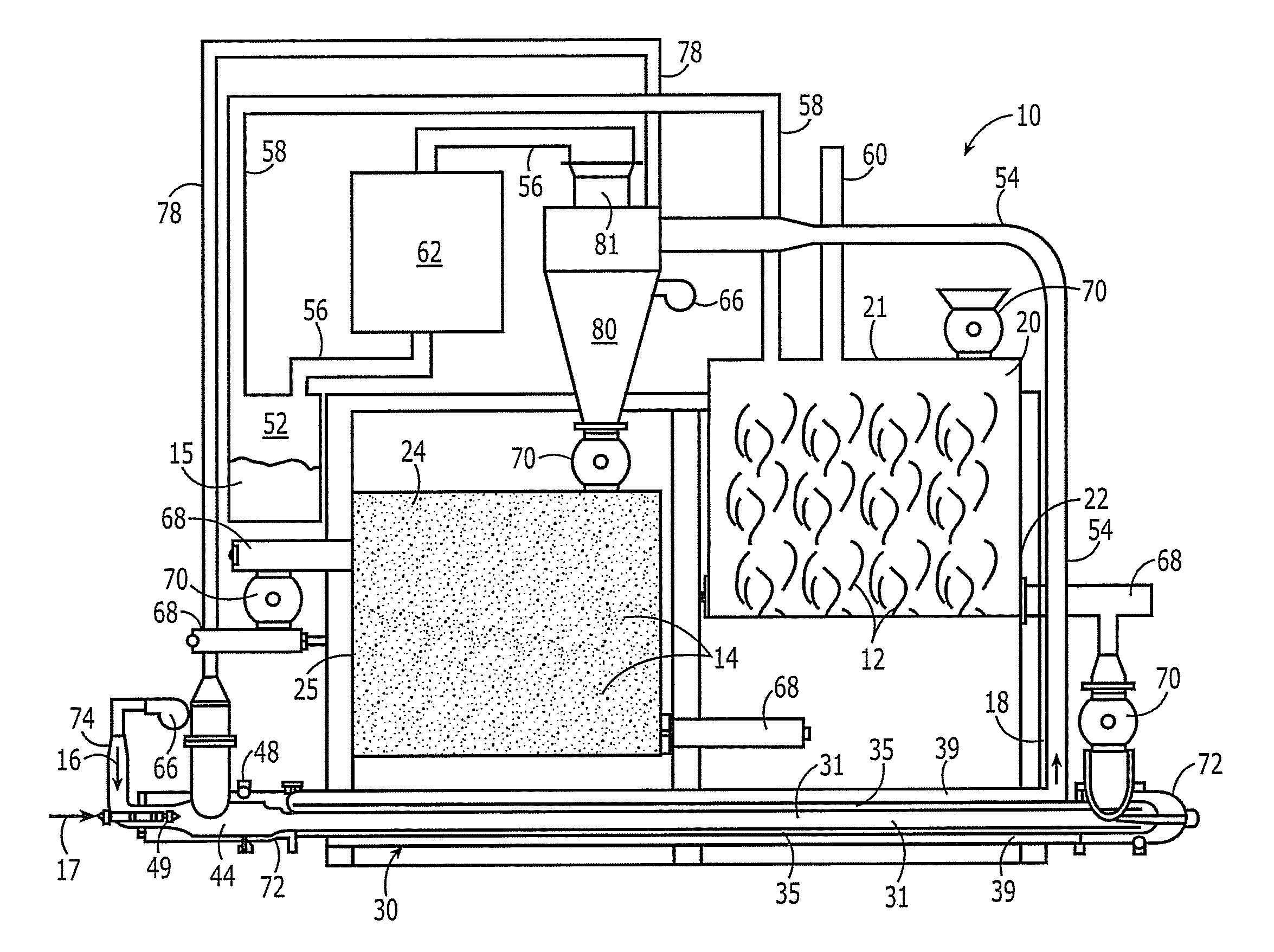
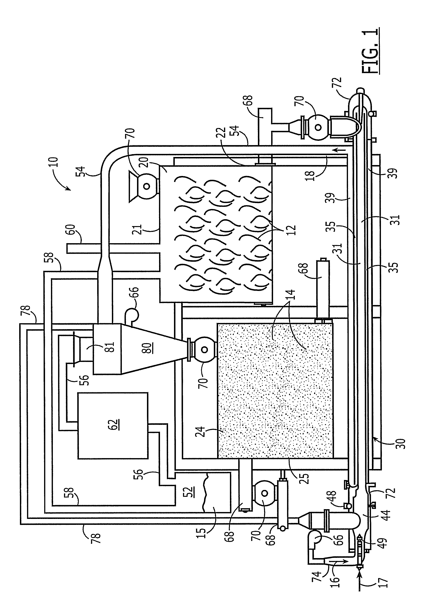
[0034]a fast pyrolysis system is depicted in FIGS. 1-4 and designated generally by reference numeral 10.

[0035]Referring now to FIG. 1, the system 10 comprises a biomass feed bin 20 for receiving and delivering biomass 12 that is to be pyrolysized. The biomass feed bin 20 is generally enclosed to provide greater control over the channeling of exhaust 18 (shown as an arrow) from pyrolytic reactions that is fed into the feed bin 20, as described below with reference to FIG. 1. The biomass 12 is fed through a top 21 of the feed bin 20 using a rotary air lock 70. The biomass 12 is delivered from the feed bin 20 by an auger 68 attached to a lower portion 22 of the biomass feed bin 20, as described below with reference to FIGS. 1 and 2. In this way, the biomass feed bin 20 continually cycles new biomass 12 through the system 10.

[0036]Continuing with FIG. 1, the biomass feed bin 20 accepts raw biomass 12. The present embodiment envisions receiving this biomass 12 primarily from sawmills, pa...

second embodiment

[0057]FIG. 5 depicts a concentric-chambered pyrolysis system, designated generally by reference numeral 110, in accordance with the present invention. In the present embodiment, substantially an entire amount of char 14 produced from pyrolytic reactions in a pyrolysis unit 30 is fed back into the system 110 to help fuel further pyrolytic reactions.

[0058]Referring now to FIG. 5, as particles of char 14 exit an open end 88 of a collection cone portion 86 of a cyclone separator 80, the char 14 enters a rotary air lock 70 attached to the open end 88. The rotary air lock 70 feeds the char 14 directly into a char feed duct 123. The char feed duct 123 leads to a char-air input duct 78. The char-air input duct 78, in turn, leads to a burn enclosure 44 of a pyrolysis unit 30. In this way, virtually all of the char 14 produced from pyrolysized biomass 12 is fed back into the system 110 and used to power further fast pyrolytic reactions. Additional fuel 17 (shown as an arrow), such as fuel oil...

embodiment 200

[0068]FIGS. 9 and 10 describe a preferred embodiment of the energy-conversion system 200 shown in FIG. 7. Referring first to FIG. 9, raw biomass 204 is ground into cubes at step 220. The ground biomass 204 is then subjected to drying 230. Optimally, the dried biomass 204 has a moisture content of no more than twelve percent. In other embodiments, steam resulting from the drying process 230 is collected for re-use by other parts of the system 200. Hot exhaust gas 320 from the fast pyrolysis system 206 is used in generating electricity 300 which, in turn, is used to aid in the drying process 230. The exhaust gas 320 has a typical temperature of approximately five-hundred degrees Fahrenheit or greater and has a typical oxygen content of approximately fifteen percent. A portion of the exhaust 320 is also used to aid in fast pyrolysizing the biomass 250. Before the exhaust 320 can be used for fast pyrolysis 250, however, it must be deoxygenated. To rid the exhaust 320 of its oxygen, a fu...


PUM


Abstract

Efficient biomass conversion systems, methods and apparatus utilize a fast pyrolysis unit installed at a sawmill or similar location where substantial quantities of biomass are generated, with the biomass generated at the sawmill fed into the fast pyrolysis unit under pyrolytic reaction conditions, and with exhaust gases containing entrained matter resulting from the pyrolytic reactions being separated into constituent char and bio-fuel constituents.

Description

CROSS-REFERENCE TO RELATED APPLICATIONS[0001]This application claims priority to provisional application Ser. No. 61 / 053,386, filed May 15, 2008, and is a continuation-in-part of application Ser. No. 12 / 361,743 filed Jan. 29, 2009.BACKGROUND[0002]The present invention relates generally to systems, apparatus, and methods for the production of energy products from carbonizable material such as biomass, particularly systems, apparatus and methods that employ fast pyrolytic reactions.[0003]Today, the United States faces substantial environmental issues from continuing reliance on polluting energy sources such as coal, natural gas, nuclear power and hydroelectric power. The burning of fossil fuels, such as coal and natural gas, results in the emission of excessive amounts of carbon dioxide into the atmosphere. The use of nuclear power raises the specter of ecological damage through the accidental release of radiation into the environment, as well as difficulties in safely disposing of sp...

Claims


Application Information

Patent Timeline
IPC IPC(8): B01J7/00C01B3/02C10J3/00C01B3/36C01B6/24
CPCC10B49/08C10B49/20C10B53/02C10C5/00Y02E50/14Y02P20/145Y02E50/10C10B47/00
Inventor THARPE, JR., JOHNNY M.
Owner AMERICAN BIO ENERGY CONVERTING
Why Eureka
Try Eureka