Ceramic cover wafers of aluminum nitride or beryllium oxide

a technology of aluminum nitride and beryllium oxide, which is applied in the direction of synthesized resin layered products, magnetic recording, and storage of records, etc., can solve the problems of residue deposits that can adversely affect other processing conditions, contaminate future processing steps, and affect so as to reduce the cleaning time, improve the life of the susceptor, and reduce the impact of wafer throughpu

Active Publication Date: 2012-08-28
APPLIED MATERIALS INC
View PDF16 Cites 10 Cited by
  • Summary
  • Abstract
  • Description
  • Claims
  • Application Information

AI Technical Summary

Benefits of technology

[0021]In other embodiments, the aluminum nitride ceramic wafer or the beryllium oxide ceramic wafer is chosen to have a dielectric value sufficient to alter the electromagnetic field to spread the plasma away from the susceptor during a cleaning operation, directing more of the plasma towards the walls of the chamber. The introduction of the aluminum nitride ceramic wafer or the beryllium oxide ceramic wafer into the chamber has a negative impact on the wafer throughput by adding the time required to load the ceramic wafer and then unload after the cleaning process. However, the redirecting of the plasma with the ceramic wafer reduces the cleaning time itself, more than making up for the amount of time required for handling of the ceramic wafer. The methods described herein may be used to increase the lifetime of a susceptor and decrease the number of times the susceptor has to be replaced, thereby reducing down time of a chamber, and thereby increasing wafer throughput.

Problems solved by technology

As these deposits build up, the residues can flake off and contaminate future processing steps.
Such residue deposits can also adversely affect other processing conditions such as deposition uniformity, deposition rate, film strength and the like.
A disadvantage of the dry cleaning operation is that it contributes to the degradation of the susceptor, which is typically made of aluminum.
However, during a plasma cleaning process, the fluorine chemistry of the process will penetrate the anodized layer and cause the formation of aluminum fluoride.
The formation of aluminum fluoride results in formation of nodules, cracks and delamination which, in turn, causes uniformity and particle problems on wafers subsequently placed on the susceptor.

Method used


Image

  • Ceramic cover wafers of aluminum nitride or beryllium oxide
  • Ceramic cover wafers of aluminum nitride or beryllium oxide
  • Ceramic cover wafers of aluminum nitride or beryllium oxide

Examples


Embodiment Construction

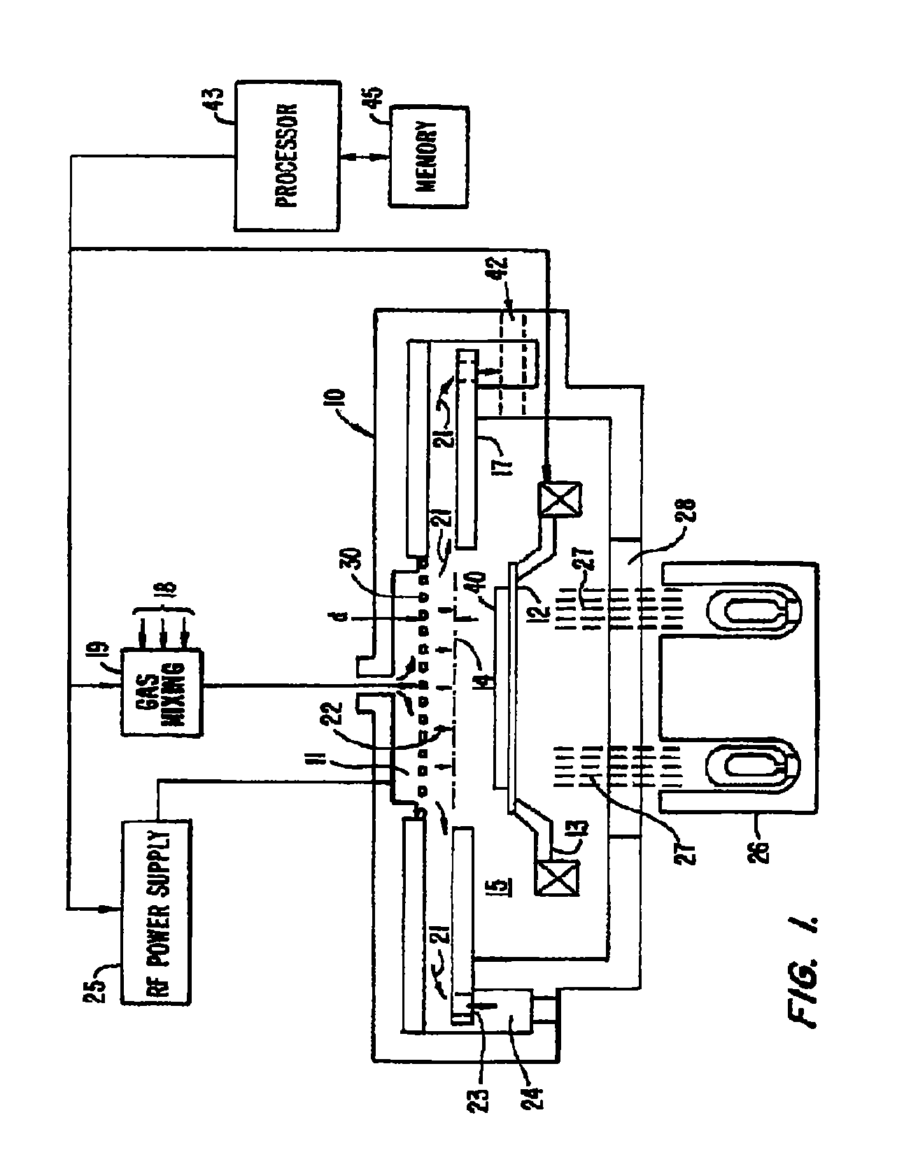
[0025]FIG. 1 depicts a suitable processing chamber for performing the methods described in embodiments. FIG. 1 which is a vertical, cross-sectional view of processing chamber 10, which is a simplified, parallel plate chemical vapor deposition (CVD) reactor having vacuum chamber 15. Processing chamber 10 contains gas inlet manifold 11 for dispersing deposition gases to a substrate or wafer that rests on susceptor 12. Susceptor 12 is highly thermally responsive and is mounted on support fingers 13 so that susceptor 12 (and the wafer supported on the upper surface of susceptor 12) can be controllably moved between a lower loading / off-loading position and an upper processing position 14 which is closely adjacent gas inlet manifold 11.

[0026]When susceptor 12 and the wafer are in processing position 14, they are surrounded by baffle plate 17 having a plurality of spaced holes 23 which exhaust into annular vacuum manifold 24. During processing, the gas flows through holes 30 of gas inlet m...


PUM

PropertyMeasurementUnit
diameteraaaaaaaaaa
thicknessaaaaaaaaaa
flatnessaaaaaaaaaa

Abstract

Embodiments of the invention provide a method and apparatus for protecting a susceptor during a cleaning operation by loading a ceramic cover substrate containing either aluminum nitride or beryllium oxide onto the susceptor before introducing the cleaning agent into the chamber. In one embodiment, an aluminum nitride ceramic cover substrate is provided which includes an aluminum nitride ceramic wafer having a thermal conductivity of greater than 160 W / m-K, a circular-shaped geometry having a diameter within a range from about 11 inches to about 13 inches, a thickness within a range from about 0.030 inches to about 0.060 inches, and a flatness of about 0.010 inches or less. The thermal conductivity may be about 180 W / m-K, about 190 W / m-K, or greater. The thickness may be within a range from about 0.035 inches to about 0.050 inches, and the flatness may be about 0.008 inches, about 0.006 inches, or less.

Description

CROSS-REFERENCE TO RELATED APPLICATIONS[0001]This application claims benefit of U.S. Ser. No. 60 / 970,250, filed Sep. 5, 2007, and U.S. Ser. No. 60 / 970,757, filed Sep. 7, 2007, which are herein incorporated by reference in their entirety.BACKGROUND OF THE INVENTION[0002]Embodiments described herein relate to a method and an apparatus for cleaning a processing chamber.DESCRIPTION OF THE RELATED ART[0003]During a chemical vapor deposition (CVD) process, the reactant gases can create compositions which deposit upon the inside surfaces of the chamber. As these deposits build up, the residues can flake off and contaminate future processing steps. Such residue deposits can also adversely affect other processing conditions such as deposition uniformity, deposition rate, film strength and the like.[0004]Accordingly, processing chambers are typically periodically cleaned to remove the residue material. Typically, etching gases are used to clean the chamber after each process or after a few pr...

Claims


Application Information

Patent Timeline
Patent Type & Authority Patents(United States)
IPC IPC(8): B32B27/32
CPCC04B35/08C04B35/581Y10T428/265C04B2235/3205C04B2235/3217C04B2235/3224C04B2235/3225C04B2235/3232C04B2235/3239C04B2235/3241C04B2235/3244C04B2235/3251C04B2235/3256C04B2235/3258C04B2235/40C04B2235/80C04B2235/94C04B2235/95C04B2235/9607C04B2235/963H01L21/02
Inventor RASHEED, MUHAMMAD M.
Owner APPLIED MATERIALS INC
Why Eureka
Try Eureka