Photoelectric conversion device, production method thereof and imaging device

a technology of photoelectric conversion and production method, applied in the field of photoelectric conversion device, a production method thereof and an imaging device, can solve the problems of reduced aperture ratio and light gathering efficiency reduction, large dark current attributable to the material used or film structure, and increase of dark current often, etc., to achieve high efficiency, low dark current, and high speed response

Active Publication Date: 2012-09-04
FUJIFILM CORP
View PDF6 Cites 0 Cited by
  • Summary
  • Abstract
  • Description
  • Claims
  • Application Information

AI Technical Summary

Benefits of technology

[0016]An object of the present invention is to provide a photoelectric conversion device and a solid-state imaging device, which are endowed with high efficiency, high-speed response and low dark current.
[0035]According to the present invention, a photoelectric conversion device and a solid-state imaging device, which are excellent in the high photoelectric conversion efficiency and high-speed responsivity and assured of low dark current, can be provided.

Problems solved by technology

In recent years, with the progress of a multi-pixel system, the pixel size and in turn, the area of a photodiode part becomes small, and this brings about problems of reduction in the aperture ratio and reduction in the light gathering efficiency.
In an organic photoelectric conversion device, it is one of key issues to obtain a high S / N ratio.
In the case of introducing a pn junction or a bulk heterostructure, an increase of dark current often arises as a problem.
However, the photoelectric conversion device of Non-Patent Document 1 is also designed with a solar cell in mind and when the technique described in this publication is directly applied to an imaging sensor, the dark current attributable to the material used or film structure is large, making it impossible to use the device as an imaging device.

Method used


Image

  • Photoelectric conversion device, production method thereof and imaging device
  • Photoelectric conversion device, production method thereof and imaging device
  • Photoelectric conversion device, production method thereof and imaging device

Examples


example 1

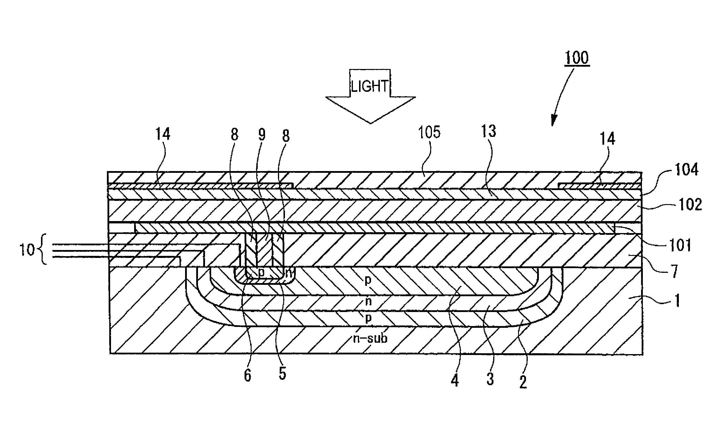
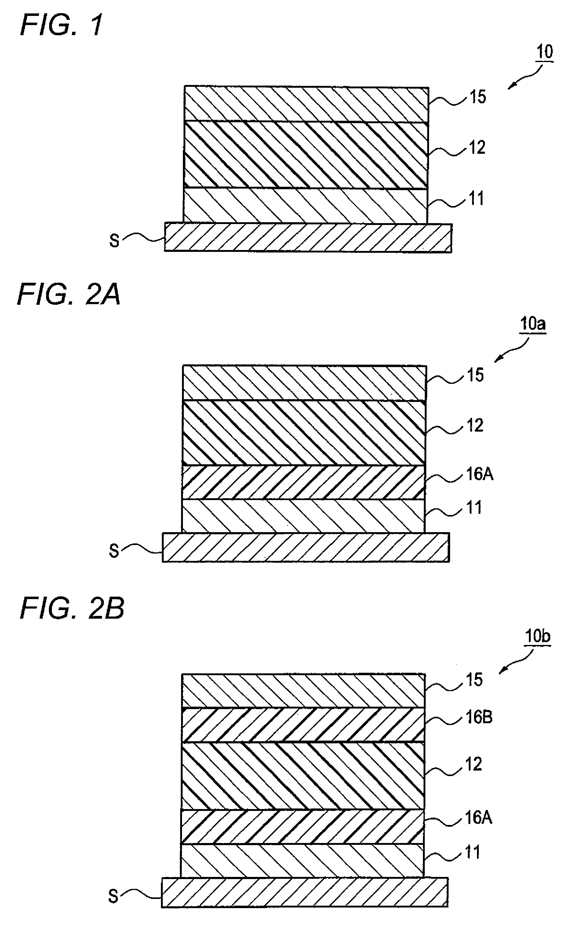
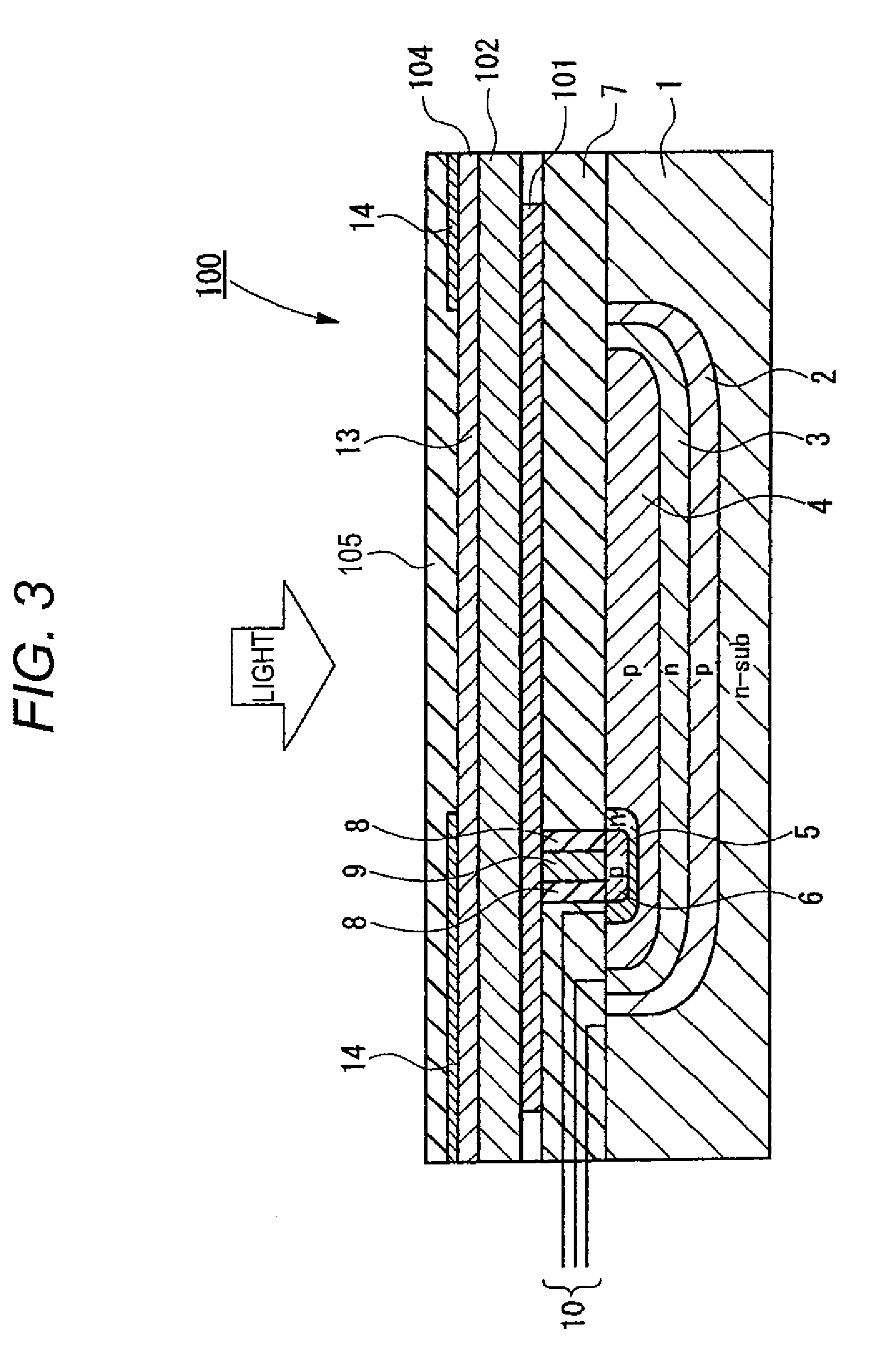
[0393]A photoelectric conversion device was produced as follows.

[0394]Amorphous ITO was deposited on a substrate by sputtering to a thickness of 30 nm to form a lower electrode. On this lower electrode, a layer formed by co-depositing Compound (I) shown below and fullerene (C60) at a vapor deposition rate of 1.7 Å / s to a thickness of 100 nm and 300 nm, respectively, in terms of a single layer was deposited by vacuum heating deposition in a state of the substrate temperature being controlled to 80° C. to form a photoelectric conversion layer. Furthermore, TPD and mMTDATA were deposited thereon to a thickness of 20 nm and 300 nm, respectively, to form an electron blocking layer. The vacuum deposition of the photoelectric conversion layer and electron blocking layer was performed at a vacuum degree of 4×10⁻⁴ Pa or less for all layers.

[0395]Thereafter, amorphous ITO was deposited thereon as an upper electrode by sputtering to a thickness of 10 nm to form a transparent upper electrode. I...

example 2

[0396]A photoelectric conversion device was produced in the same manner except that in the deposition of the photoelectric conversion layer of Example 1, the co-deposited layer of Compound (1) and fullerene (C60) was deposited at a substrate temperature of 80° C. and a vapor deposition rate of 13.6 Å / s.


PUM


Abstract

Provided is a photoelectric conversion device comprising an electrically conductive film, a photoelectric conversion film, and a transparent electrically conductive film, wherein said photoelectric conversion film contains a crystallized fullerene or fullerene derivative, and said crystallized fullerene or fullerene derivative is oriented in the (111) direction perpendicularly to the film surface of said electrically conductive film.

Description

BACKGROUND OF THE INVENTION[0001]1. Field of the Invention[0002]The present invention relates to a photoelectric conversion device, a production method thereof and an imaging device.[0003]2. Description of the Related Art[0004]As for the solid-state imaging device, there is widely used a flat light-receiving device where photoelectric conversion sites are two-dimensionally arrayed in a semiconductor to form pixels and a signal generated by photoelectric conversion in each pixel is charge-transferred and read out according to a CCD or CMOS format. The conventional photoelectric conversion site is generally formed, for example, by forming pn junction in a semiconductor such as Si.[0005]In recent years, with the progress of a multi-pixel system, the pixel size and in turn, the area of a photodiode part becomes small, and this brings about problems of reduction in the aperture ratio and reduction in the light gathering efficiency. As for the measure to enhance the aperture ratio and the...

Claims


Application Information

Patent Timeline
Patent Type & Authority Patents(United States)
IPC IPC(8): H01L51/44H01L51/48H01L31/14
CPCB82Y10/00H01L51/0047H01L51/4253H01L51/0059H01L51/006H01L51/4246Y02E10/549Y02P70/50H10K85/215H10K85/631H10K85/633H10K30/30H10K39/32H10K30/211
Inventor MITSUI, TETSURO
Owner FUJIFILM CORP
Why Eureka
Try Eureka