
Lithographically defined microporous carbon structures

a microporous carbon and structure technology, applied in the field of porous carbon materials, can solve the problems of limiting the advantage of modifying the structure with functional materials such as catalytic particles or large biomolecules, and reducing the mass transport (linear diffusion) profile, and achieves excellent electrochemical behavior, high surface area, and enormous flexibility

Active Publication Date: 2013-01-08
NAT TECH & ENG SOLUTIONS OF SANDIA LLC
View PDF7 Cites 13 Cited by
  • Summary
  • Abstract
  • Description
  • Claims
  • Application Information

AI Technical Summary

Benefits of technology

The patent describes a method for making porous carbon electrodes with uniform dimensions and controllable pore sizes. These electrodes are strong, conductive, and have excellent electrochemical behavior. The method also allows for the creation of structures over a wide range of sizes, which can be customized for different applications. The structure of the electrodes can be controlled at the lithography step, making them optimal for their specific uses. The 3-D porous carbon can also be patterned at different geometries, which allows for increased mass transport and full usage of cataltic particles. The unique nanostructures provide increased pathways for reaction species to diffuse and react throughout the entire electrode surfaces, making them effective for applications such as batteries, supercapacitors, and hydrogen storage devices.

Problems solved by technology

However, due to small pore diameters, pore nonuniformity, and possible hydrophobicity, diffusion or penetration of electrolyte is often limited to a certain depth in many synthetic (nano)mesoporous materials which can limit any advantage of modifying the structures with functional materials such as catalytic particles or large biomolecules.
While smaller structures and pores can be used to increase active surface areas they are often made at a high density resulting in decreased mass transport (linear diffusion) profiles due to overlapping diffusion layers.

Method used


Image

  • Lithographically defined microporous carbon structures
  • Lithographically defined microporous carbon structures
  • Lithographically defined microporous carbon structures

Examples


Embodiment Construction

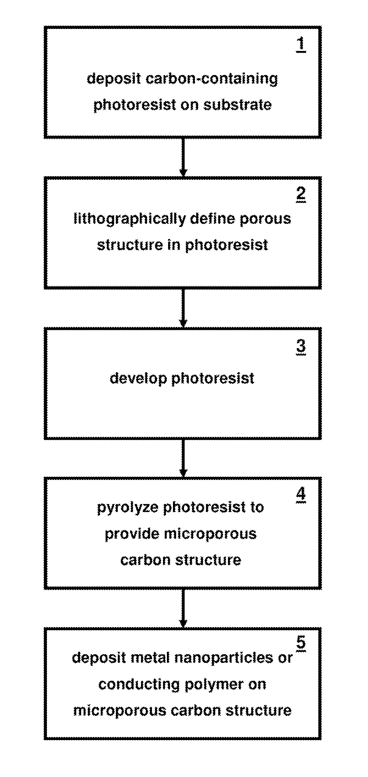
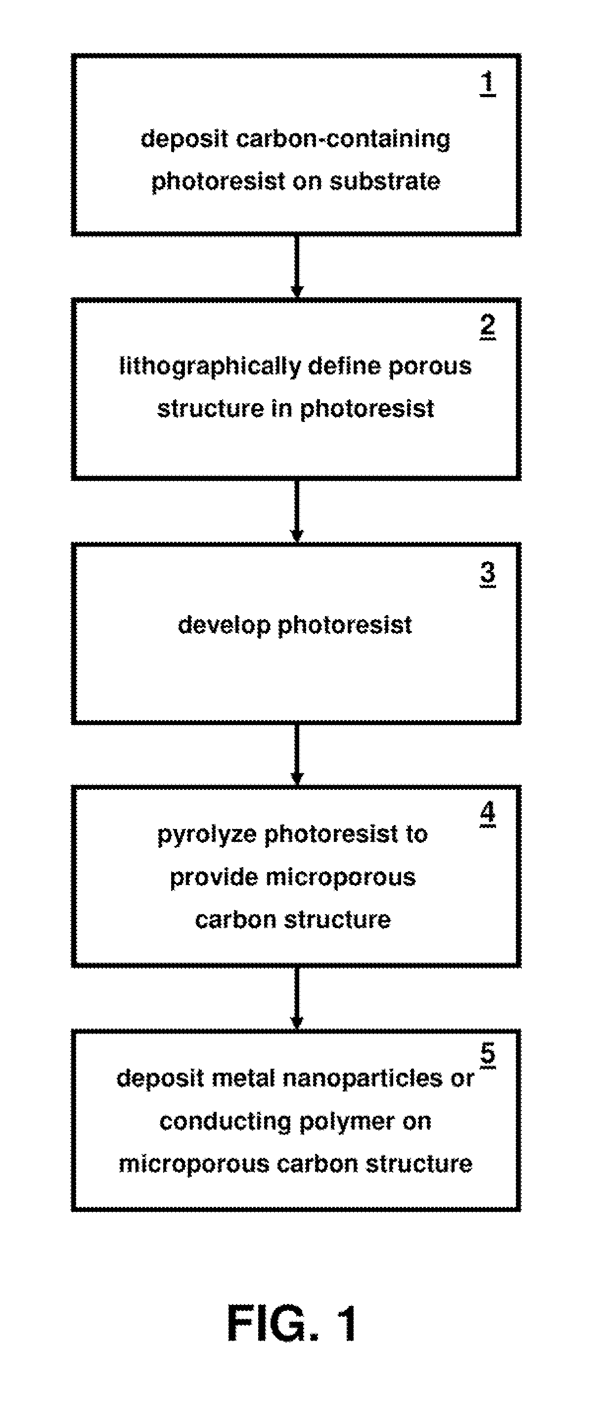
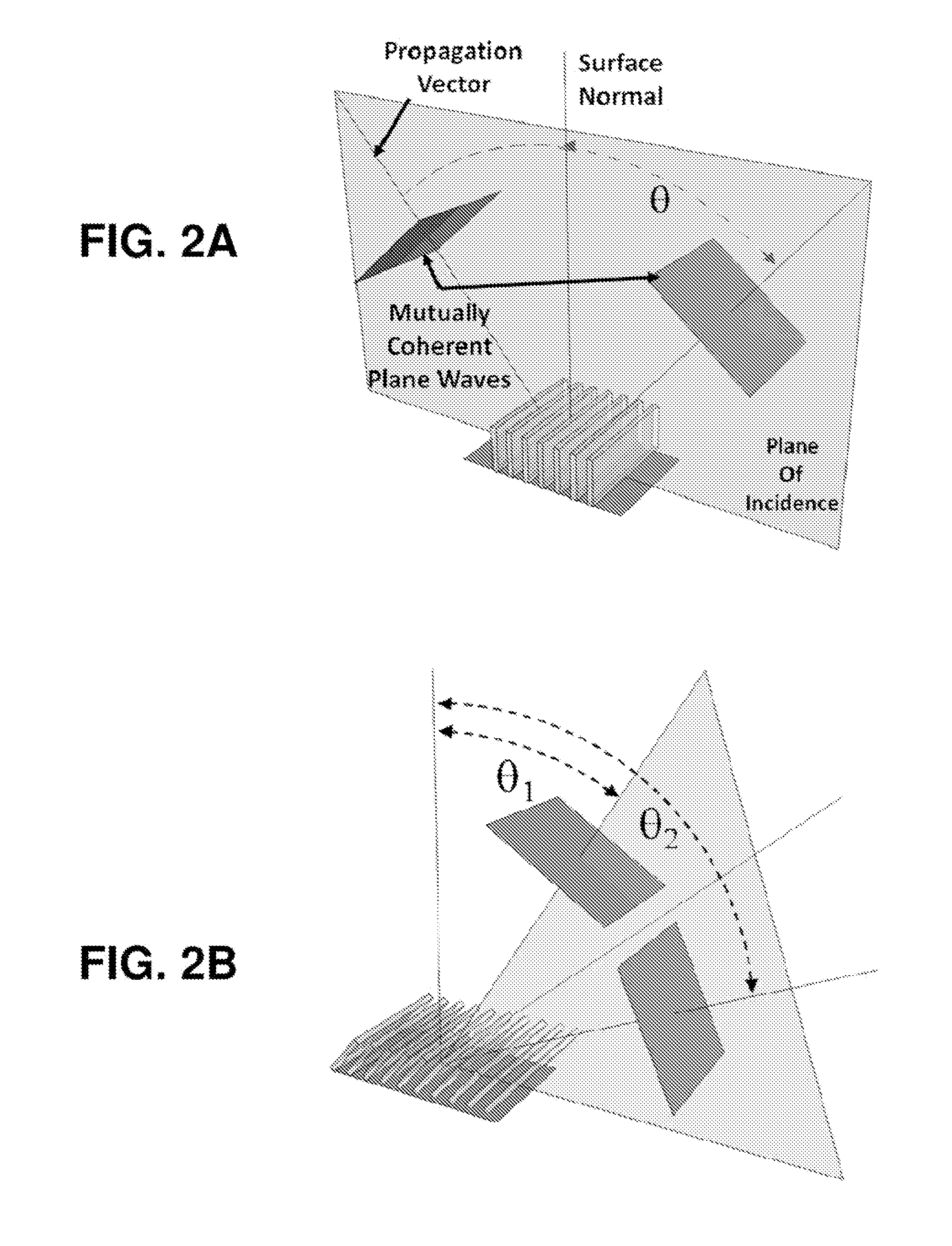
[0024]The present invention is directed to lithographically defined porous pyrolyzed photoresist films. Pyrolyzed photoresist films have similar properties as glassy carbon electrodes with an advantage that they can be lithographically defined. Therefore, the invention is further directed to a lithographically defined microporous carbon electrode and to the deposition and electrochemical properties of metal nanoparticles or conducting polymers on these electrodes. The fabrication method is capable of producing large area (e.g., 10's cm2), sub-micrometer porous carbon films. Interferometric lithography can be used to pattern thick photoresist films into 3-D periodic lattices. These structures can then converted to carbon via pyrolysis under flowing forming gas. See S. Ranganathan et al., J. Electrochem. Soc. 147, 277 (2000), which is incorporated herein by reference. During pyrolysis, the non-carbon species in the resist polymer backbone are removed, while the bulk of the carbon rema...


PUM

PropertyMeasurementUnit
temperatureaaaaaaaaaa
pore sizeaaaaaaaaaa
pore sizeaaaaaaaaaa

Abstract

A lithographic method is used to fabricate porous carbon structures that can provide electrochemical electrodes having high surface area with uniform and controllable dimensions, providing enormous flexibility to tailor the electrodes toward specific applications. Metal nanoparticles deposited on the surface of the porous carbon electrodes exhibit ultra small dimensions with uniform size distribution. The resulting electrodes are rugged, electrically conductive and show excellent electrochemical behavior.

Description

CROSS-REFERENCE TO RELATED APPLICATION[0001]This application claims the benefit of U.S. Provisional Application No. 61 / 292,037, filed Jan. 4, 2010, and U.S. Provisional Application No. 61 / 288,907, filed Dec. 22, 2009, both of which are incorporated herein by reference.STATEMENT OF GOVERNMENT INTEREST[0002]This invention was made with Government support under contract no. DE-AC04-94AL85000 awarded by the U.S. Department of Energy to Sandia Corporation. The Government has certain rights in the invention.FIELD OF THE INVENTION[0003]The present invention relates to porous carbon materials and, in particular, to lithographically defined microporous carbon structures.BACKGROUND OF THE INVENTION[0004]The special nature of the C—C bond can lead to various polymorphic forms of carbon, such as graphite, glassy-carbon, fullerenes (such as buckyballs), carbon nanotubes and diamond. In addition to the intrinsic material properties of carbon, functionalized films can be produced through chemical ...

Claims


Application Information

Patent Timeline
Patent Type & Authority Patents(United States)
IPC IPC(8): G03F7/26
CPCG03F7/0015H01M4/0471H01M4/583H01M4/8817G03F7/091H01M4/9083H01M4/926H01M4/8825Y02E60/50Y02E60/10
Inventor BURCKEL, DAVID BRUCEWASHBURN, CODY M.POLSKY, RONENBROZIK, SUSAN M.WHEELER, DAVID R.
Owner NAT TECH & ENG SOLUTIONS OF SANDIA LLC
Learn More