
Image forming apparatus and process cartridge

a technology of image forming apparatus and process cartridge, which is applied in the direction of electrographic process apparatus, corona discharge, instruments, etc., can solve the problems of large size and high cost of the tandem drum system, easy deterioration of chargeability and sensitivity of the image bearing member, and high cost, so as to achieve high environmental durability and high responsive optical attenuation

Inactive Publication Date: 2013-02-19
RICOH KK
View PDF41 Cites 2 Cited by
  • Summary
  • Abstract
  • Description
  • Claims
  • Application Information

AI Technical Summary

Benefits of technology

The patent text describes an image forming apparatus that can produce high-quality images consistently over a long period of time, even if some of its image bearing members are used more frequently than others. Additionally, the apparatus is designed to be resistant to oxidized gas and can maintain its color tone, background clarity, and image quality. The goal is to create an image forming apparatus that is both highly responsive and durable, while also reducing costs.

Problems solved by technology

However, the tandem drum system is large in size and expensive at cost.
Also, this effect accompanies a new problem, which is about improvement of the sensitivity and stability of the image bearing member.
Generally, the chargeability and the sensitivity of an image bearing member easily deteriorate and the voltage at irradiated portion thereof tends to rise during repetitive use of the image bearing member.
This leads to a problem of usage bias (uneven frequency of usage) among the image bearing members in the full color image forming apparatus.
This easily leads to deterioration of the optical attenuation property of an image bearing member relatively heavily used in comparison with the other image bearing members and results in variance in color tone of a full color image which is formed by overlapping colors during repetitive use.
In addition, oxidized gas produced by a charging device chemically affects the photosensitivity of an image bearing member, which leads to deterioration of the photosensitivity and production of abnormal images having defects such as deterioration of definition and image flow.
As described above, when the characteristics of an image bearing member are unstable over repetitive use and the image bearing member has been used for a long period of time, an image forming apparatus using the image bearing member produces images having a problem with the quality, resulting in variation in color tone or back ground fouling.

Method used


Image

  • Image forming apparatus and process cartridge
  • Image forming apparatus and process cartridge
  • Image forming apparatus and process cartridge

Examples


manufacturing example 1

Illustrated Derivative No. 20

[0283]2.68 g (10.0 mmol) of naphthalene-1,4,5,8-tetracarbonic dianhydride (manufactured by Tokyo Chemical Industry Co., Ltd.) and 3.68 g (20.0 mmol) of 1,1-diphenylhydradine (manufactured by Tokyo Chemical Industry Co., Ltd.) are added to 30 ml of N,N′-dimethylformamide and stirred at 60° C. in argon atmosphere for 2 hours. 100 ml of water is added to precipitate a crystal and the precipitated crystal is filtered followed by drying by a reduced pressure heating drier to obtain 3.43 g (yield: 57.1%) of brown coarse crystal. The resultant is subject to silica gel column treatment (eluting solvent: mixture solvent of toluene and ethyl acetate with a ratio of 20 to 1 in volume) followed by re-crystallization by toluene and drying by the reduced pressure heating drier. 7.02 g (yield: 29.7%) of the diimide derivative (illustrated derivative No. 20: orange and red crystal) represented by the following Chemical Structure (a) is obtained.

[0284]

[0285]The element a...

example 1

[0289]The liquid application for an undercoating layer, the liquid application for a charge generation layer and the liquid application for a charge transport layer, each having the following recipe, are sequentially applied to an aluminum drum having a diameter of 30 mm and a length of 340 mm by a dip coating method. Subsequent to drying, an image bearing member No. 1 is obtained which has an undercoating layer of 4.5 μm, a charge generation layer of 0.2 μm and a charge transport layer of 28 μm.

Recipe for Liquid Application for Undercoating Layer

[0290]

Powder of titanium dioxide (Tipaque CR-EL,400 partsmanufactured by Ishihara Sangyo Kaisha Ltd.)Melamine resin (Super Beckamine G821-60, 65 partsmanufactured by DIC Corporation)Alkyd resin (Beckolite M6401-50, manufactured120 partsby DIC Corporation)2-butanone400 parts

Recipe for Liquid Application for Charge Generation Layer

[0291]

X type non-metal phthalocyanine 10 parts(FastogenBlue8120B, manufactured byDIC Corporation)Polyvinylbutyral...

examples 2 to 15

[0299]Image bearing members Nos. 2 to 15 of Examples 2 to 15 are manufactured and evaluated in the same manner as in Example 1 except that the naphthalene tetracarbonic acid diimide derivative of the illustrated compound No. 4 for use in the liquid application for the charge transport layer is changed to the respective compounds shown in Table 3 below. The results of Examples 2 to 15 are shown in Table 3.

[0300]

TABLE 3Initial stageAfter 80,000 printsVoltageVoltageImageatatEx-bearingIllustratedlightlightamplememberderivativeportionDotportionDotNo.No.No.(V)definition(V)definition114170518052221555180533315551755445155517545571805185566918051804771114551605881317051804991517551854101017160518051111211655180412122316051805131325145517541414301555170515153415051805


PUM


Abstract

An image forming apparatus including at least an image bearing member having a substrate having a photosensitive layer thereon, the image bearing member to bear a latent electrostatic image on a surface thereof, a charging device to the surface of the image bearing member, an irradiation device to irradiate the surface of the image bearing member with light to form a latent electrostatic image thereon, a development device to develop the latent electrostatic with toner to obtain a developed image, a transfer device to transfer the developed image to a recording medium, and a cleaning device to clean the surface of the image bearing member, wherein the photosensitive layer includes naphthalene tetracarbonic acid diimide derivative as a charge transport material represented by the following Chemical Structure (1):In the Chemical Structure (1), Z represents a group represented by the following Chemical Formula (1):or the following Chemical Formula (2):—R9  Chemical Formula (2).In the Chemical Structure (1), and the Chemical Formulae (1) and (2), R1, R2, R3, R4 and R9 each, independently, represent a substituted or non-substituted alkyl group or a substituted or non-substituted aromatic hydrocarbon group, R5, R6, R7 and R8 each, independently, represent hydrogen atom, a substituted or non-substituted alkyl group, or a substituted or non-substituted aromatic hydrocarbon group, and R1 and R2 and R3 and R4 optionally share a bond connectivity to form a substituted or non-substituted heterocyclic group including a nitrogen atom.

Description

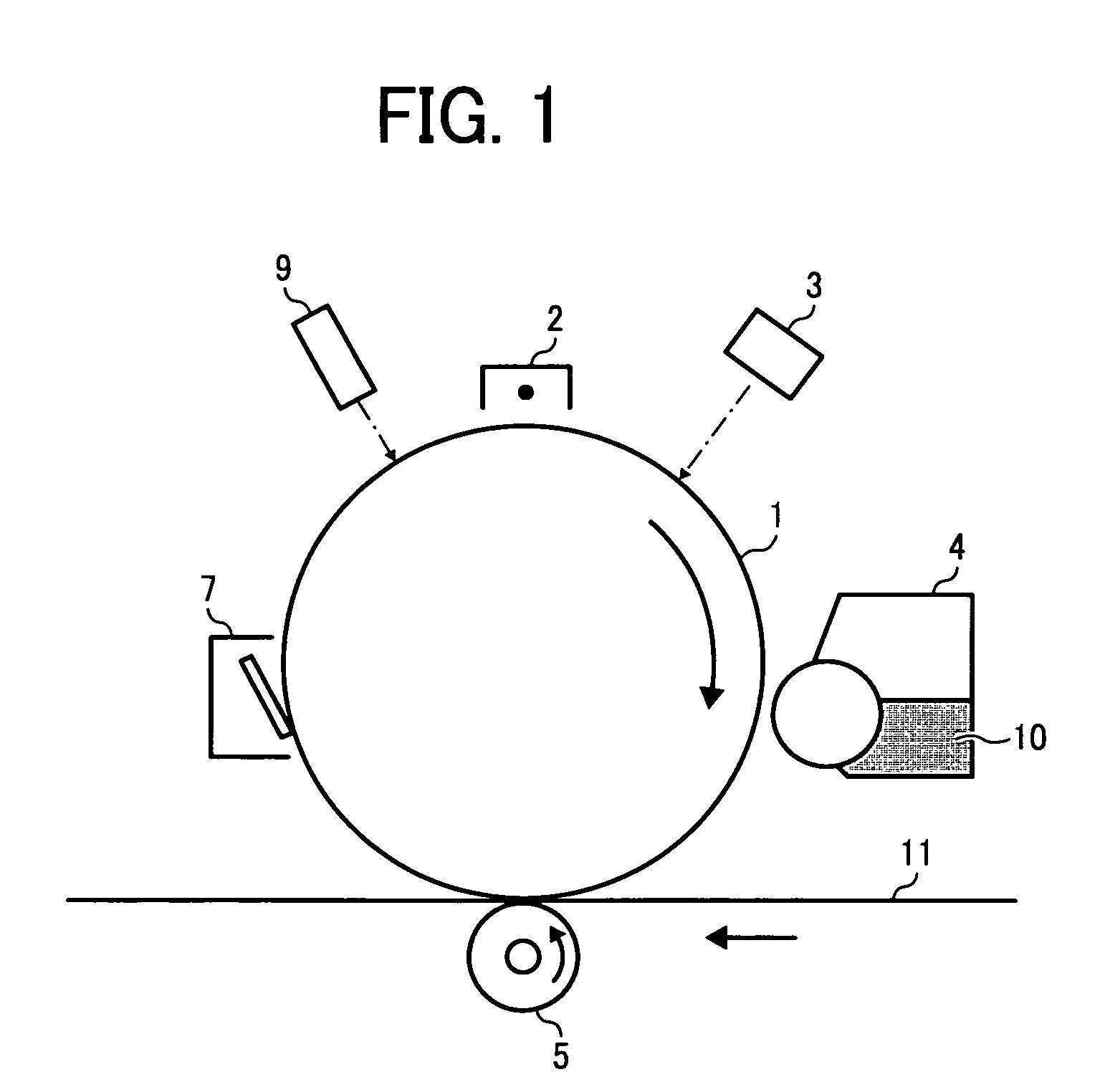
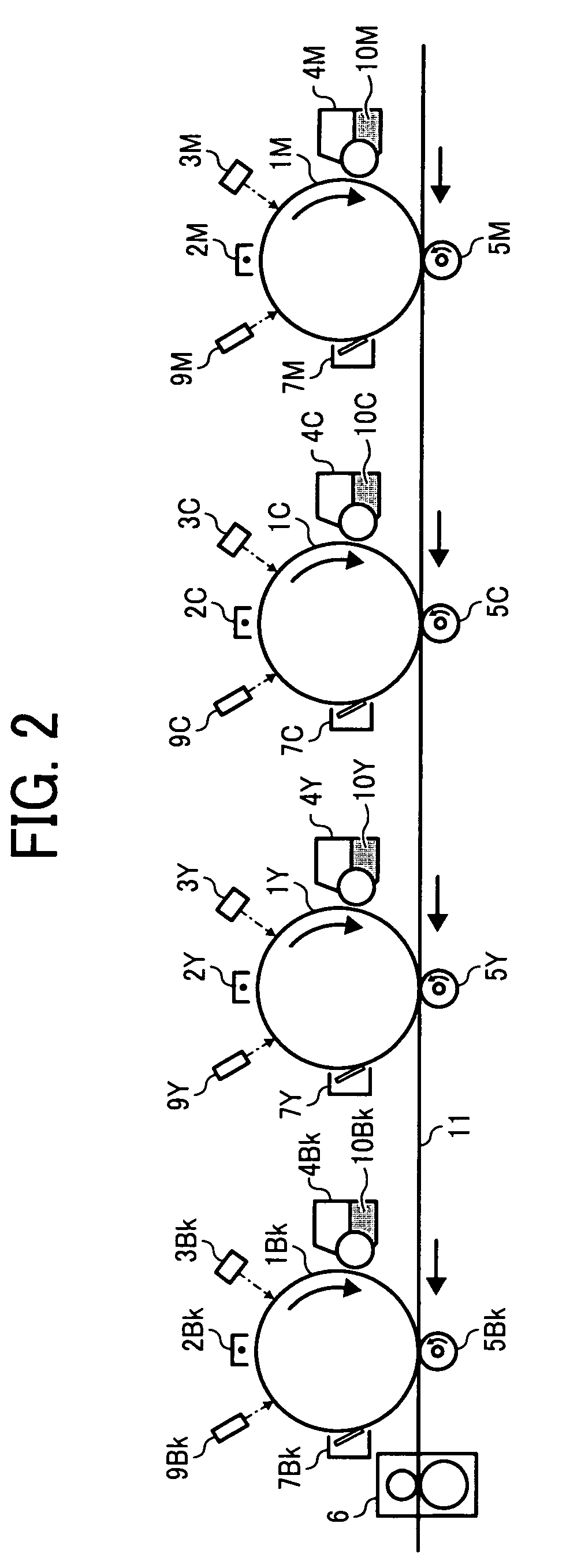
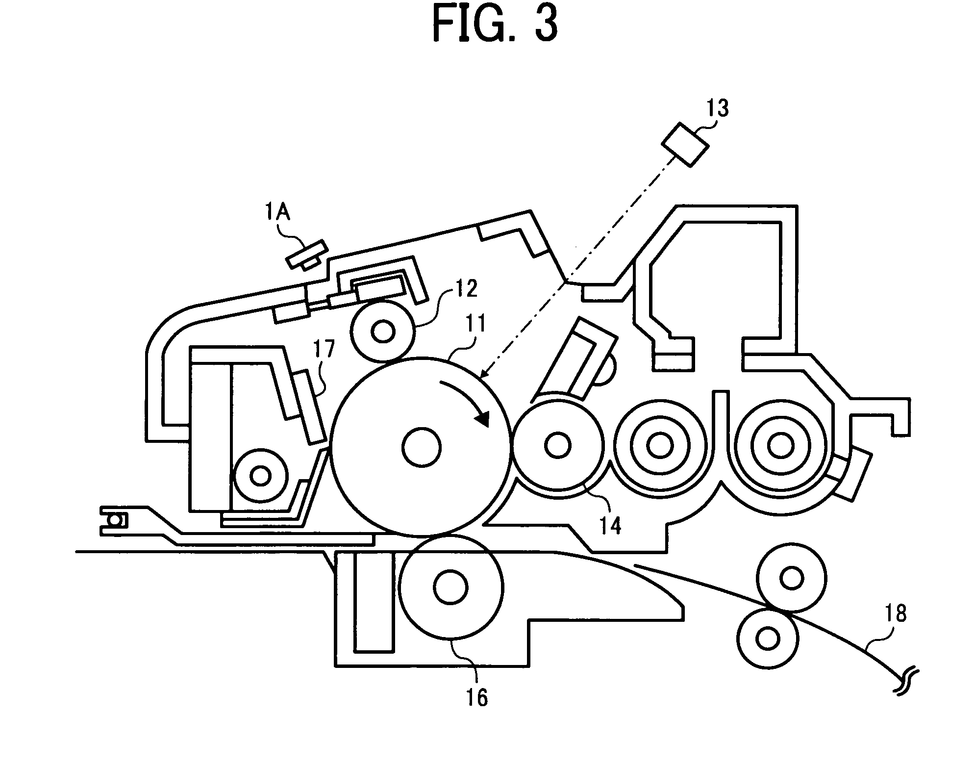
BACKGROUND OF THE INVENTION[0001]1. Field of the Invention[0002]The present invention relates to an image forming apparatus and a process cartridge.[0003]2. Discussion of the Background[0004]A full color image forming apparatus generally employs one of the two typical systems.[0005]One is referred to as a single or single-drum system in which one image bearing member is installed with four color development devices. In this system, a four color (cyan, magenta, yellow and black) toner image is formed on the image bearing member and transferred to a transfer medium directly or via an intermediate transfer body. Devices or members arranged around the image bearing member, which are, for example, a charging member, an irradiation device, a transfer device, a cleaning device and a fixing device, can be shared in the process of producing each color toner image. Therefore, this system can be small-sized and manufactured at a small cost in comparison with a tandem system described below.[00...

Claims


Application Information

Patent Timeline
Patent Type & Authority Patents(United States)
IPC IPC(8): G03G15/00G03G5/06
CPCG03G5/0614G03G5/0648G03G5/0651G03G15/751
Inventor KURIMOTO, EIJISHIMOYAMA, KEISUKESHIMADA, TOMOYUKIOHTA, MASAFUMITANAKA, YUUJI
Owner RICOH KK
Learn More