Time base generator and method for providing a first clock signal and a second clock signal

a time base and clock signal technology, applied in the field of control systems, can solve the problems of amplitude fluctuations and even cancellations, intermediate frequency signals suffer distortions, and the phase difference between clock signals is not predictable, and the time base jitter must be maintained low

Active Publication Date: 2013-03-05
SIEMENS AG
View PDF10 Cites 17 Cited by
  • Summary
  • Abstract
  • Description
  • Claims
  • Application Information

AI Technical Summary

Benefits of technology

[0015]The loop lock time is shorter because the adjustment of the frequency of the voltage-controlled oscillator is performed after a much shorter time than the time to reach coincidence between the first and second clock signals. Furthermore, the cycle durations or phasing of the first and second auxiliary signals do not have to be detected coincidentally which means that arbitrary, non-coincident signals can be processed in the same loop.

Problems solved by technology

The jitter of the time base has to be maintained low because, when the jitter becomes significant with respect to the period of the carrier signal (microwave), the intermediate frequency signal suffers distortions, amplitude fluctuations and even cancellations.
However, as the oscillators start up, the phase difference between the clock signals is not predictable.
Zero phase detector errors may diminish the merits of the digital solution and the measurement time is increased because a waiting time for zero phase detection has to be added.
The thermal drift of the components results in time delay variations over temperature.
However, the analog signals having slower variation still produces a larger jitter from the voltage noise than the digital signals with fast transitions.
Accordingly, a major disadvantage of this conventional technique may be the long response time because the frequency multiplication is performed by a phase-locked loop (PLL) and each frequency adjustment can only be made after the two signals are checked around the coincidence moment when N periods of the first clock signal=M periods of the second clock signal.
Several corrections are necessary to lock the PLL, and when large N and M divider ratios are required, it takes a very long time to bring the PLL into lock.
Another disadvantage may arise from the use of digital circuits that limit the circuit operation to integer numbers.

Method used


Image

  • Time base generator and method for providing a first clock signal and a second clock signal
  • Time base generator and method for providing a first clock signal and a second clock signal
  • Time base generator and method for providing a first clock signal and a second clock signal

Examples


first embodiment

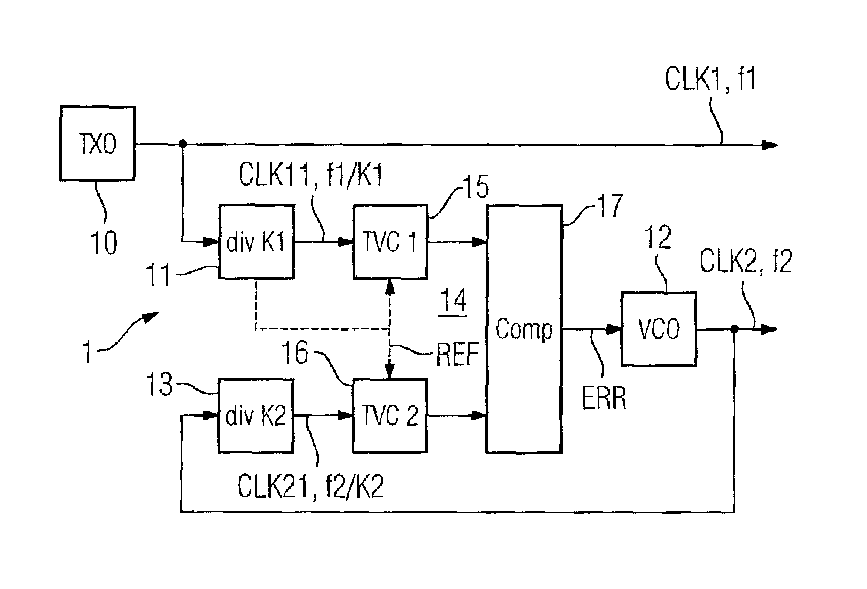
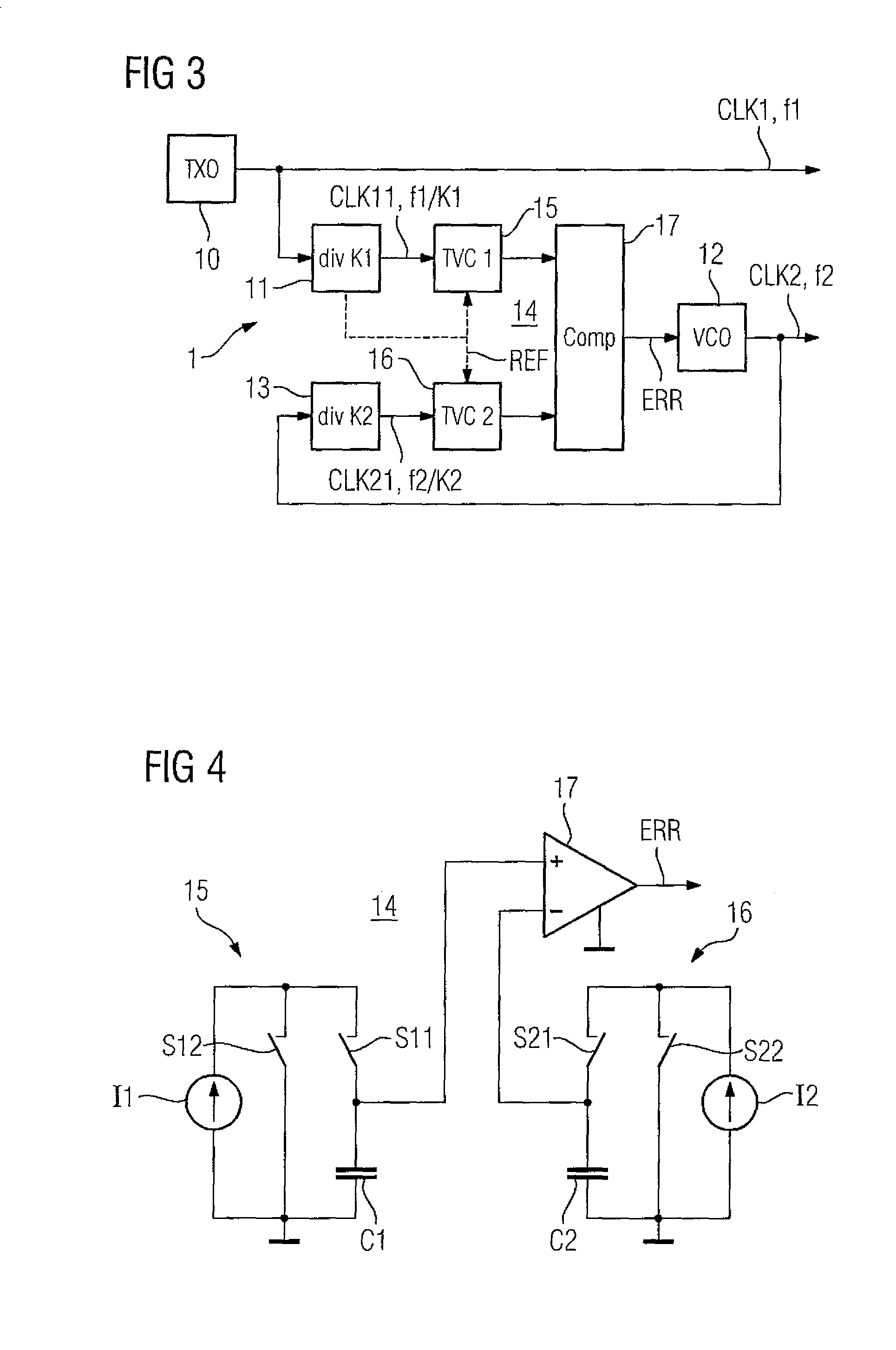
[0031]In a first embodiment, the time-to-voltage converters 15 and 16 generate a voltage proportional to the cycle durations of the respective first and second auxiliary signals CLK11, CLK21. Thus, for example, switch S11 is closed and switch S12 is open when and as long as the first auxiliary signal CLK11 is high so that the voltage over capacitor C1 linearly increases with time. When the first auxiliary signal CLK11 drops to a low level, switch S11 is opened and switch S12 is closed so that the capacitor C1 holds the voltage. After a hold time, switch S11 is closed to discharge capacitor C1. The second time-to-voltage converter 16 works equally for the second auxiliary signal CLK21, however, the detected cycle durations of the first and second auxiliary signals CLK11, CLK21 are differently weighted. The different weighting may be achieved in that the constant current sources 11, 12 provide different currents, the capacitors C1, C2 have different capacities and / or the voltage compa...

second embodiment

[0034]In a second embodiment, the phasing of the first and second auxiliary signals CLK11 and CLK21 is used to control the voltage-controlled oscillator 12. The time to voltage conversion can be started simultaneously for both time-to-voltage converters 15, 16 at an arbitrary reference moment by a reference signal REF related to the first clock signal CLK1 and stopped independently at the rising (or falling) edge of the first auxiliary signal CLK11 for the first time-to-voltage converter 15 and at the rising (or falling) edge of the second auxiliary signal CLK21 for the second time-to-voltage converter 16. The position of the rising (or falling) edge of the second auxiliary signal CLK21 in relation with the rising (or falling) edge of the first auxiliary signal CLK11 is adjusted and maintained by individually weighting and comparing the voltages from the time-to-voltage converters 15 and 16 and controlling the voltage-controlled oscillator 12. The edges of the auxiliary signals CLK1...


PUM


Abstract

A time base generator and method for providing a first clock signal and a second clock signal comprising generating the first clock signal at a first clock frequency, dividing the first clock frequency by a first integer to produce a first auxiliary signal, dividing the second clock signal by a second integer to produce a second auxiliary signal, generating an error signal by individually weighting and comparing cycle durations or phasing of the first and second auxiliary signals, and generating the second clock signal by a voltage-controlled oscillator controlled by the error signal such that two clock signals of slightly different frequencies with defined time or phase delay are provided.

Description

BACKGROUND OF THE INVENTION[0001]1. Field of the Invention[0002]The present invention relates to control systems and, more particularly, to a time base generator for providing a first clock signal and a second clock signal, and to a method for providing the first and second clock signals.[0003]2. Description of the Related Art[0004]Pulse radar ranging systems, such as those described in U.S. Pat. No. 4,521,778 to Knepper, provide distance or level measurements based on the direct measurement of the propagation time of microwave pulses transmitted to and reflected from a target, e. g., the surface of a fill material in a container. The propagation time for distances of a few meters is in the nanosecond range. As a result, a special time transformation procedure is required to enable measurement of these short time periods. The microwave pulses are transmitted to the target at a repetition rate or transmit clock frequency which is supplied by a transmit clock generator. In a signal mi...

Claims


Application Information

Patent Timeline
Patent Type & Authority Patents(United States)
IPC IPC(8): H03L7/06
CPCG01S7/28G06F1/06H03L7/097H03L7/10H03L7/18H03L7/12
Inventor BURCEA, GEORGE
Owner SIEMENS AG
Why Eureka
Try Eureka