Fabrication of a floating rocker MEMS device for light modulation

a technology of light modulation and fabrication method, which is applied in the direction of microelectromechanical systems, instruments, coatings, etc., to achieve the effects of improving contrast ratio, reducing the number of pixels, and fast switching array of mirrors

Active Publication Date: 2013-07-16
QORVO US INC
View PDF7 Cites 4 Cited by
  • Summary
  • Abstract
  • Description
  • Claims
  • Application Information

AI Technical Summary

Benefits of technology

[0009]The current disclosure shows how to make a fast switching array of mirrors for projection displays. Because the mirror does not have a via in the middle connecting to the underlying spring support, there is an improved contrast ratio that results from not having light scatter off the legs or vias like existing technologies. Because there are no supporting contacts, the mirror can be made smaller making smaller pixels that can be used to make higher density displays. In addition, because there is not restoring force from any supporting spring support, the mirror stays in place facing one or other direction due to adhesion. This means there is no need to use a voltage to hold the mirror in position. This means that less power is required to run the display.
[0010]To operate the display each pixel can be twinned with an SRAM memory cell so the information required for the pixels next action is stored into the SRAM. The fact there is no restoring force also means full mechanical latching based on stiction. This allows for the data under the pixel to be written prior to reset for better memory efficiency and better overall optical efficiency. When the memory state of the SRAM is changed, the pixel won't follow because the adhesion keeps it in place until the reset pulse is applied. This reset pulse is large enough to overcome the adhesion force.

Problems solved by technology

In addition, because there is not restoring force from any supporting spring support, the mirror stays in place facing one or other direction due to adhesion.

Method used


Image

  • Fabrication of a floating rocker MEMS device for light modulation
  • Fabrication of a floating rocker MEMS device for light modulation
  • Fabrication of a floating rocker MEMS device for light modulation

Examples


Embodiment Construction

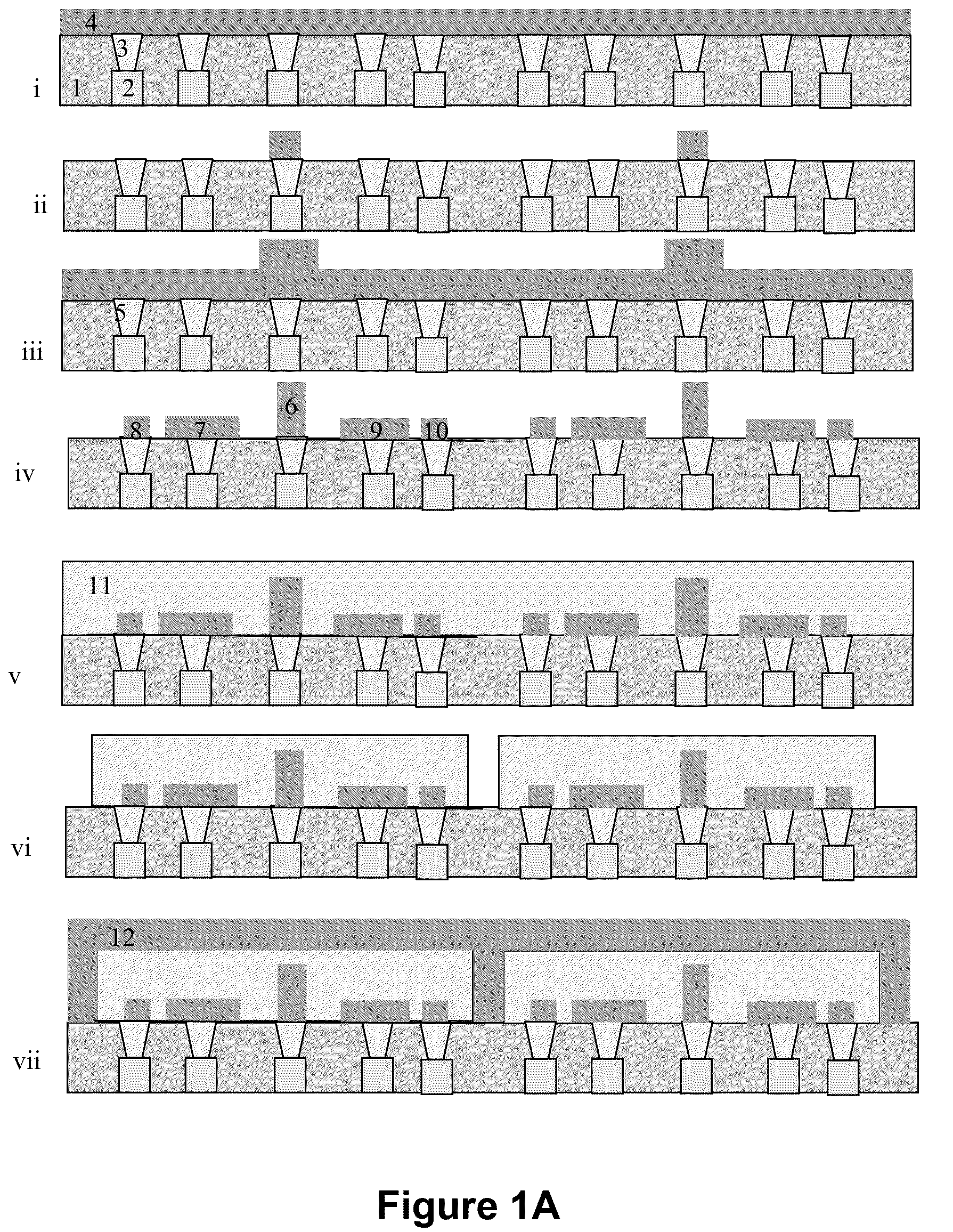
[0029]FIG. 1A shows how the floating rocker device could be manufactured. Initially the substrate material is prepared with vias 3 from metal tracks 2 leading up through an insulating layer that could be silicon dioxide or silicon nitride or some other insulating or semi-insulating layer. This could be the interlayer dielectric of a CMOS device with active CMOS addressing for the mirror array defined underneath. The first MEMS layer to be deposited could be a TiN layer which will be used for part of the base for the post 6 which the rocker will land on when released. The first MEMS layer is patterned using optical lithography processes usually found in semiconductor processing plant. The optical lithography processes could include wet etching of the metal layer under a patterned resist layer or dry etching of the layer using a plasma etch process.

[0030]After the first MEMS layer is etched to leave the base of the post 6, a second layer which may also be TiN, will be deposited. The s...


PUM


Abstract

The current disclosure shows how to make a fast switching array of mirrors for projection displays. Because the mirror does not have a via in the middle connecting to the underlying spring support, there is an improved contrast ratio that results from not having light scatter off the legs or vias like existing technologies. Because there are no supporting contacts, the mirror can be made smaller making smaller pixels that can be used to make higher density displays. In addition, because there is not restoring force from any supporting spring support, the mirror stays in place facing one or other direction due to adhesion. This means there is no need to use a voltage to hold the mirror in position. This means that less power is required to run the display.

Description

CROSS-REFERENCE TO RELATED APPLICATIONS[0001]This application claims benefit of U.S. Provisional Patent Application Ser. No. 61 / 236,373 (CK063L), filed Aug. 24, 2009, which is herein incorporated by reference.BACKGROUND OF THE INVENTION[0002]1. Field of the Invention[0003]The embodiments discussed herein cover the fabrication and use of a free floating element in a micro electro mechanical system (MEMS) that is un-tethered during the release process. The embodiments can be used in a rocker design where the free floating element lands on a rocking post and has two stable positions, either leaning to the left or leaning to the right. Such a structure can be used as a bi-stable switch for optical applications. An array of these floating rockers can be used for video projectors. These projectors can be used in conjunction with a computer for presentations or for video entertainment or in high definition applications as a cinema projector. The same technology can also be used for back pr...

Claims


Application Information

Patent Timeline
Patent Type & Authority Patents(United States)
IPC IPC(8): G02B26/00
CPCB81C1/00317G02B26/0833G02B26/0841B81B2201/042B81C2203/0145B81C2203/0136B81B3/00B81C1/00G02B26/00
Inventor SMITH, CHARLES GORDONKNIPE, RICHARD L.
Owner QORVO US INC
Why Eureka
Try Eureka