Method of manufacturing a nozzle plate for a liquid ejection head

a technology of liquid ejection and nozzle plate, which is applied in the direction of recording apparatus, instruments, inking apparatus, etc., can solve the problems of unstable flying rate of ink droplets and fluctuation of the size of ink droplets, so as to minimize the fluctuation of the nozzle diameter, and reduce the fluctuation of the nozzle length

Active Publication Date: 2014-11-11
KONICA MINOLTA INC
View PDF20 Cites 0 Cited by
  • Summary
  • Abstract
  • Description
  • Claims
  • Application Information

AI Technical Summary

Benefits of technology

[0022]According to the invention described in embodiments 1, 2, and 5, the present nozzle plate achieves the following effects. The etching rate during Si anisotropic dry etching of the small diameter portion of a base material is lower than that of the large diameter portion. When the large diameter portion is formed via Si anisotropic dry etching, the etching rate is lowered while Si anisotropic dry etching reaches the base material of the small diameter portion. Consequently, even though etching is excessively carried out while considering fluctuation of the large diameter portion due to Si anisotropic dry etching, it is retarded that the base material of the small diameter portion becomes thinner, whereby it is possible to make the length of the small diameter portion the thickness of the base material. Consequently, it is possible to realize the length of the small diameter portion of the targeted accuracy without fluctuation.
[0023]According to the invention described in embodiment 8, even in a nozzle plate having a small ejection hole of an internal diameter of the small diameter portion of less than 10 μm, by forming the thin liquid repellent film of a thickness of less than 100 nm, it is possible to minimize the fluctuation of the nozzle diameter due to intrusion of the liquid repellent film into the ejection hole. In addition, by decreasing the fluctuation of the nozzle length, due to any fluctuation of thickness of the liquid repellent film, it is possible to avoid the resulting effects being applied to the ejection of liquid droplets. Namely, it is possible to minimize fluctuation of ejection capability among nozzles. As described above, since it is possible to minimize fluctuation of the nozzle length, it becomes possible to maintain constant electric field intensity of the tip portion of the meniscus formed on the ejection hole of the nozzle. Further, by decreasing the thickness of the liquid repellent film, it is possible to restrain an increase in the practical nozzle length and the fluid channel resistance, whereby it is possible to restrain an increase in the pressure necessary to eject liquid droplets and drive voltage of a pressure generating means.
[0024]According to the invention described in embodiment 9, by forming the fluorosilane based liquid repellent film on the SiO2 film, it is possible to modify the resulting film into a desired monomolecular film. Further, by employing the fluorosilane based liquid repellent film, it is possible to modify the resulting nozzle plate to one which exhibits no change of liquid repellency over a period.
[0025]According to the invention described in embodiment 10, by forming the thin liquid repellent film, even though intrusion into the nozzle during formation of the liquid repellent film may occur, adverse effects to ejection capability are lowered, whereby application specifically to a minute nozzle of less than 6 μm becomes possible.
[0026]According to the invention described in embodiment 11, by forming the thin liquid repellent film, even though intrusion into the nozzle during formation of the liquid repellent film may occur, adverse effects to ejection capability are lowered, whereby application specifically to a minute nozzle of less than 4 μm becomes possible.
[0027]Further, according to the invention described in embodiment 12, by employing the nozzle plate for the liquid ejection head provided with the nozzle plate exhibiting the above effects, it is possible to constitute a liquid ejection head.

Problems solved by technology

For example, when ink adheres to the periphery of the ejection hole of the nozzle plate to generate non-uniform ink puddles, problems occur in which, for example, when non-uniform ink puddles are generated via adhesion of the ink at the periphery of the ejection hole of the nozzle plate, the ejection direction of ink droplets is bent, the ink droplet size fluctuates, and the flying rate of ink droplets become unstable.

Method used


Image

  • Method of manufacturing a nozzle plate for a liquid ejection head
  • Method of manufacturing a nozzle plate for a liquid ejection head
  • Method of manufacturing a nozzle plate for a liquid ejection head

Examples


example 1

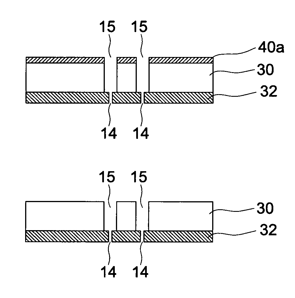
[0129]An example to manufacture nozzle plate 1 will now be described, employing FIGS. 4 and 5. Initially, formation of small diameter portions 14 is described with reference to FIG. 4. On one surface of 200 μm thick Si substrate 30, formed was a 5 μm thick SiO2 film as second base material 32 (FIG. 4(a)). Plasma CVD was employed as the forming method.

[0130]Subsequently, a 0.3 μm thick Ni film which was film 34 converted to etching mask 34a was formed via a sputtering method (FIG. 4(b)). On the Ni film was formed photoresist pattern 36 via a photolithographic process (FIG. 4c)). Thereafter, formed was a Ni film pattern, which was etching mask 34a to form, on the SiO2 film which was second base material 32, small diameter portions 14 at a diameter of 5 μm, carrying ejection holes as openings via etching (FIG. 4(d)).

[0131]By employing etching mask 34a, the SiO2 film, which was second base material 32, was subjected to dry etching in which CF4 was employed as the reaction gas, whereby s...

example 2

[0139]The liquid ejection apparatus according to the present invention was prepared by employing each of the nozzle plates in which the thickness of the SiO2 film, where the small diameter portions were formed and the diameter of the small diameter portions in Example 1 were variously changed (Embodiment 1 in Table 1). Incidentally, 16 nozzles were formed in one nozzle plate.

[0140]Further, the liquid ejection apparatus according to the present invention was prepared employing a nozzle plate in which the liquid repellent film was replaced with a 2 μm thick one employing fluorine based liquid repellent agents (Embodiment 2 in Table 1).

[0141]By employing the liquid ejection apparatus prepared as above, ejection performance was evaluated. A liquid to be ejected was an ink incorporating 52% by weight of water, 22% by weight of ethylene glycol, 22% by weight of propylene glycol, 3% by weight of a dye (CI Acid Red 1), and 1% by weight of surface active agents. Further, the ejection perform...


PUM

PropertyMeasurementUnit
internal diameteraaaaaaaaaa
diameteraaaaaaaaaa

Abstract

A manufacturing method of nozzle plate for liquid ejection head includes, providing a substrate having a first base material of Si and a second base material, of which the etching rate in Si anisotropic dry etching is lower then that of Si, provided on one side of the first base material, forming a film as a second etching mask on the surface of the second base material, forming a second etching mask pattern having a small-diameter opening shape in the second etching mask film, etching until the etching part is extended through the second base material, forming a film as a first etching mask film on the surface of the first base material, forming a first etching mask pattern having a large-diameter opening shape in the first etching mask film, and Si anisotropic dry etching until the etched part is extended through the first base material.

Description

[0001]This application is the United States national phase application of International Application PCT / JP2007 / 066022 filed Aug. 17, 2007.TECHNICAL FIELD[0002]The present invention relates to a manufacturing method of a nozzle plate for a liquid ejection head, a nozzle plate for a liquid ejection head, and a liquid ejection head.BACKGROUND ART[0003]In recent years, high speed and high resolution printing is demanded for ink-jet system printers. Semiconductor processes for silicon substrates, which are microfabrication technologies in the micromachine fields, are applied to the forming method of ink-jet system recording heads employed in the above printers. Consequently, many methods have been proposed which form fine-structured bodies via applying etching onto silicon substrates. Of these, known is a method to form nozzles of an ink-jet system head in such a manner that a silicon substrate is subjected to the following types of etching.[0004](1) A resist film is formed on the surfac...

Claims


Application Information

Patent Timeline
Patent Type & Authority Patents(United States)
IPC IPC(8): B41J2/16B41J2/14
CPCB41J2/1628B41J2/1623B41J2202/11B41J2/1642B41J2/1632B41J2/1646B41J2/1433B41J2/161B41J2/162B41J2/1631B41J2/1645Y10T29/49401
Inventor YANATA, ATSURODOI, ISAO
Owner KONICA MINOLTA INC
Why Eureka
Try Eureka