
Optical amplifier

a technology of optical amplifier and laser amplifier, which is applied in the direction of instruments, active medium shape and construction, laser details, etc., can solve the problems of laser amplifiers that do not have the function of reshaping a degraded pulse waveform of a signal light, limited operation speed of electronic components, and increased power consumption, etc., to suppress the degradation of s/n ratio, suppress noise, and high-quality optical signal amplification

Active Publication Date: 2015-06-23
NIPPON TELEGRAPH & TELEPHONE CORP
View PDF1 Cites 36 Cited by
  • Summary
  • Abstract
  • Description
  • Claims
  • Application Information

AI Technical Summary

Benefits of technology

This patent is about a new technology for amplifying optical signals using a special type of amplifier called a phase sensitive amplifier. This amplifier uses a special nonlinear optical effect called parametric amplification to amplify a specific component of the signal. It is designed to improve the quality of optical signals while also reducing the influence of noise. This technology can be used in optical communication to improve the transmission distance and speed of signals. It can also suppress the degradation of signals due to the beat noise between ASE light and signals, resulting in improved signal quality. Overall, this technology can lead to better performance and higher efficiency in optical signal amplification.

Problems solved by technology

However, this regenerating optical repeater had a disadvantage in that operation speed of an electronic component was limited when converting an optical signal to an electric signal, and power consumption was increasing as transmission speed became higher for example.
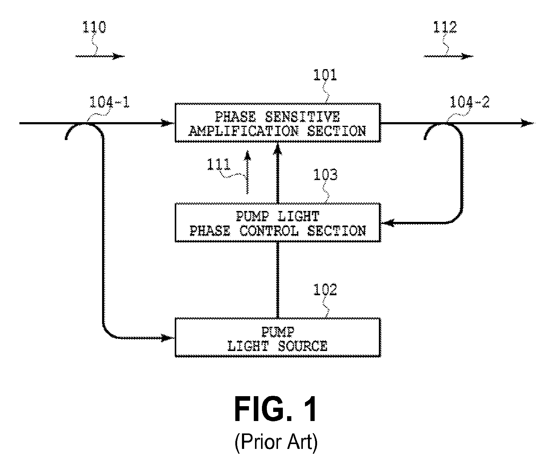
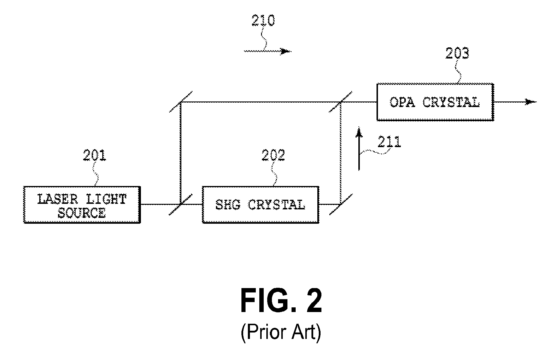
However, these laser amplifiers do not have a function to reshape a degraded pulse waveform of a signal light.
Furthermore, in the case of these laser amplifiers, amplified spontaneous emission, which is generated unavoidably and randomly, is irrespectively mixed with a signal component, thus causing a reduction of the S / N ratio of the signal light by at least 3 dB before and after the amplification.
They cause an increase of a bit error rate and the decrease of the transmission quality in the digital transmission systems.

Method used


Image

  • Optical amplifier
  • Optical amplifier
  • Optical amplifier

Examples


first embodiment

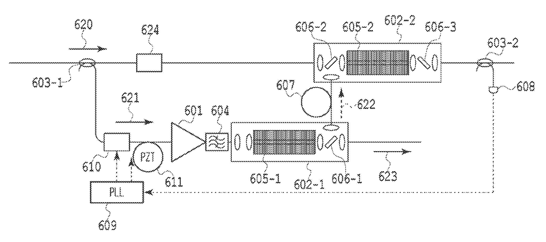
[0148]FIG. 6 shows the configuration of this embodiment. In this embodiment, in order to obtain sufficient power to generate nonlinear optical effect from weak laser light used for optical communication, an erbium-doped fiber amplifier (EDFA) 601 is used to amplify fundamental wave light 621. The amplified fundamental wave light 621 is input into the first second-order nonlinear optical element 602-1 to thereby cause the generation of the second harmonic wave 622. The signal light 620 and the second harmonic wave 622 are input into the second second-order nonlinear optical element 602-2 to thereby perform optical parametric amplification, thus performing phase sensitive amplification. The configuration of the phase sensitive amplifier as described above is a basic feature of the invention of this application.

[0149]Although the details of the configuration shown in FIG. 6 will be described later, the use of the configuration as described above provides an effect as described below th...

second embodiment

[0167]FIG. 9 shows the configuration of this embodiment. By using the waveform shaping effect of the phase sensitive amplifier according to the present invention, even when a modulator which causes chirping to a signal is used, a signal can be sent with being removed the chirping of the signal. The output from an external cavity semiconductor LD (ECL) 930 is intensity-modulated with an electro-absorption (EA) modulator for generating a NRZ signal at a data rate of 40-Gbit / s. Thereafter, a phase sensitive amplifier similar to the phase sensitive amplifier according to the first embodiment is used to amplify the modulation signal to thereby constitute a transceiver.

[0168]Electro-absorption (EA) modulators can be manufactured in a large amount because these modulators made of semiconductor. However, since these modulators use the electric field absorption, a frequency chirp component is superposed on a modulated signal, thus resulting in degraded signal quality. Specifically, the trans...

third embodiment

[0175]FIG. 12 shows the configuration of this embodiment. The signal light 1240 with data modulation propagates through a transmission medium such as optical fibers. FIG. 12 shows a configuration example to apply this phase sensitive amplifier as a repeater amplifier to compensate for the loss of the light intensity in the transmission medium.

[0176]When a phase sensitive amplifier is located closer with a light source for a signal light, the light source can be used as a fundamental wave light by dividing the light from the light source. However, when the phase sensitive amplifier is used as a repeater optical amplifier for an optical transmission, a phase synchronization system, which described below for an example, must be used to synchronize the phase of fundamental wave light and phase of the signal light in the phase sensitive amplifier.

[0177]In this embodiment, a light which is generated by combining two polarization components is used as an input signal light. One polarizatio...


PUM

PropertyMeasurementUnit
angleaaaaaaaaaa
angleaaaaaaaaaa
diameteraaaaaaaaaa

Abstract

The phase sensitive amplifier according to the present invention is a phase sensitive amplifier that uses the optical mixing using a nonlinear optical effect to amplify the signal light. The phase sensitive amplifier according to the present invention includes: the first second-order nonlinear optical element; and the second second-order nonlinear optical element. The first second-order nonlinear optical element causes the fundamental wave light to generate second harmonic light used as pump light and separates only the second harmonic light. The second second-order nonlinear optical element includes a multiplexer to multiplex the signal light with the second harmonic light and spectrally separates only the amplified signal light. The multiplexed signal light and second harmonic light are used subjected to parametric amplification.

Description

TECHNICAL FIELD[0001]The present invention relates to an optical amplifier. Specifically, the present invention relates to an optical amplifier used in an optical communication system and an optical measurement system as well as an optical transceiver and an optical receiver including this optical amplifier.BACKGROUND ART[0002]In a conventional optical transmission system, a regenerating optical repeater has been used to regenerate a signal attenuated through optical fibers. The regenerating optical repeater converts an optical signal to an electric signal, and then discriminates the digital signal in order to regenerate an optical signal. However, this regenerating optical repeater had a disadvantage in that operation speed of an electronic component was limited when converting an optical signal to an electric signal, and power consumption was increasing as transmission speed became higher for example.[0003]For solving this problem, a fiber laser amplifier or a semiconductor laser ...

Claims


Application Information

Patent Timeline
Patent Type & Authority Patents(United States)
IPC IPC(8): H01S3/067G02F1/35H01S3/00G02F1/39H01S3/108G02F1/37H01S3/23
CPCG02F1/39G02F1/3532G02F1/3534G02F1/3544H01S3/06754H01S3/0092H01S3/1083G02F1/3536G02F1/37G02F2001/392H01S3/2391G02F1/392
Inventor ASOBE, MASAKIUMEKI, TAKESHIENBUTSU, KOUJITOKURA, AKIOMIYAMOTO, YUTAKATAKARA, HIDEHIKOTAKENOUCHI, HIROKAZUTOMITA, ISAO
Owner NIPPON TELEGRAPH & TELEPHONE CORP
Learn More