Unlock instant, AI-driven research and patent intelligence for your innovation.

Method for increasing density of aligned carbon nanotubes

a carbon nanotube and density technology, applied in the field of nanoscale electronic devices manufacturing, can solve the problems of low density, low density, and inability to produce high-quality high-density aligned carbon nanotubes, and achieve the effect of increasing the density of carbon nanotubes

Active Publication Date: 2016-05-17
PEKING UNIV
View PDF4 Cites 0 Cited by
  • Summary
  • Abstract
  • Description
  • Claims
  • Application Information

AI Technical Summary

Benefits of technology

This method significantly increases the density of carbon nanotubes parallel to the substrate, reducing defects and material loss, while maintaining uniform lengths and excellent electronic properties, achieving densities suitable for high-performance nano devices and integrated circuits.

Problems solved by technology

CNFET based on a single carbon nanotube has low drive current, and thus is easily disturbed by external parasitic capacitance, which results in slow speed.
Conventional CNT manufacturing technologies, however, cannot produce high-quality high-density aligned carbon nanotubes.
Thus the direct-growth method cannot produce high density and highly aligned CNTs.
This method involves purification, ultrasonic treatment, and modification, which make the product CNTs very short and contain lots of defects.
Thus the LB membrane method is also not suitable for manufacturing highly aligned high-density CNTs for fabricating high performance electronic devices.
Nevertheless, this method can only increase the density of the carbon nanotubes along the direction perpendicular to the substrate.
Moreover, the step of physically separating the carbon nanotubes from the elastic film may work for high density intertwined carbon nanotubes (aligned perpendicular to the substrate, i.e. CNT forest), but cannot work with lower density carbon nanotubes aligned parallel to the substrate.
Furthermore, the disclosed method suffers large material loss because the carbon nanotubes are strongly attracted to and adhered to the elastic film.
In sum, the disclosed method is unsuitable for making high density, high quality carbon nanotube arrays that are aligned parallel to substrate, which are essential for fabricating electronic devices.

Method used


Image

  • Method for increasing density of aligned carbon nanotubes
  • Method for increasing density of aligned carbon nanotubes
  • Method for increasing density of aligned carbon nanotubes

Examples


implementation example 1

[0046]PDMS is used as a stretchable material.

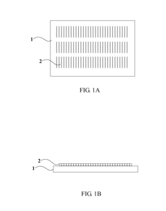
[0047]1. An array of parallel aligned carbon nanotubes 2 is grown on a quartz substrate 1 using CVD (as shown in FIGS. 1A and 1B). Examples of catalysts used in CVD include CuCl2 solution, FeCl3 solution, and iron deposited by electron beam evaporation. Common sources of carbon include CH4, C3H7OH, etc.

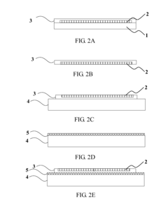
[0048]2. The array of nanotube array is transferred to PDMS (FIGS. 2A-2E). (1) PMMA 600K 3 is spin-coated on the array of parallel aligned carbon nanotubes 2 grown on the quartz substrate 1 at a rotation speed at 2000 rad / s (as shown in FIG. 2A). After PMMA dries naturally, the composite is immersed in a HF buffer (7:1) solution for about 48 hours to etch the quartz substrate 1. A composite of a PMMA film 3 and the carbon nanotubes 2 is obtained (as shown in FIG. 2B). (2) The composite is then immersed in deionized water for 10 minutes to remove residual HF remained on the PMMA film 3. Then the PMMA film 3 is attached to a stretched PDMS fi...

implementation example 2

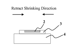
[0053]A shape memory alloy is used as stretchable material.

[0054]1. A shape memory alloy with critical temperature higher than PMMA's glass transition temperature is selected. Suitable materials include TiNi base shape memory alloy, etc. The shape memory alloy is stretched at room temperature.

[0055]2. Same as step 1 in Implementation Example 1, an array of aligned carbon nanotubes 2 is grown on a quartz substrate 1 as shown in FIGS. 1A and 1B.

[0056]3. The array of aligned carbon nanotubes is transferred onto a shape memory alloy: (1) an electron-beam resist PMMA 3 600K is spin-coated on the carbon nanotubes 2 grown on the quartz substrate 1 at a rotation speed of 2000 rad / s. After drying, the resulting composite (shown in FIG. 2A) is immersed into a HF buffer solution for 48 hours to dissolve the quartz substrate 1. A composite of a PMMA film 3 and carbon nanotubes 2 is obtained as shown in FIG. 2B. (2) The composite is immersed in deionized water for 10 minutes to remove residual H...


PUM

PropertyMeasurementUnit
thicknessaaaaaaaaaa
densityaaaaaaaaaa
temperatureaaaaaaaaaa

Abstract

The present application relates to a method of increasing density of aligned carbon nanotubes. Firstly, aligned carbon nanotubes grown on a substrate is transferred to a stretched retractable film. The retractable film is then shrunk along a direction which is perpendicular to the alignment direction of the carbon nanotubes to obtain high density carbon nanotubes. The array of aligned carbon nanotubes is finally transferred from the retractable film to a target substrate. The disclosed method can efficiently obtain high-density high-quality aligned carbon nanotubes at low cost.

Description

CROSS-REFERENCES TO RELATED APPLICATIONS[0001]This application claims the benefit of CN patent application No. 201410154960.3 filed on Apr. 17, 2014, entitled “Method for Increasing Density of Aligned Arrays of Carbon Nanotubes”, which is incorporated herein by reference in its entirety.BACKGROUND OF THE INVENTION[0002]The present application relates to technologies for manufacturing nano-scale electronic devices, and in particular, to methods of obtaining high-density aligned carbon nanotubes suitable for making such devices.[0003]Carbon nanotubes (CNT) are a one-dimensional (1D) material having ultra-long electron mean free path. Comparing to conventional silicon-based Complementary Metal Oxide Semiconductor (CMOS) field-effect transistors, carbon nanotube field-effect transistors (CNFET) have extraordinary electronic performance and controllability over static charges, which is a hopeful to replace silicon-based chip semiconductor technologies.[0004]CNFET based on a single carbon...

Claims


Application Information

Patent Timeline
Patent Type & Authority Patents(United States)
IPC IPC(8): H05H1/00B82Y30/00C01B31/02B82Y40/00
CPCB82Y40/00C01B31/0253C01B31/0226B82Y30/00C01B32/168
Inventor SI, JIAZHANG, ZHIYONGPENG, LIANMAO
Owner PEKING UNIV