Large scale insulated desalination system

a desalination system and large-scale technology, applied in vacuum distillation separation, separation processes, vessel construction, etc., to achieve the effects of reducing the overall energy requirement, low conductive and convection heat loss, and increasing the efficiency of distillation

Active Publication Date: 2016-08-30
FLO ONICS LLC
View PDF8 Cites 12 Cited by
  • Summary
  • Abstract
  • Description
  • Claims
  • Application Information

AI Technical Summary

Benefits of technology

[0041]The primary objective of the present invention is to provide a means of increasing the overall efficiency of large scale desalination systems by significantly reducing the energy input requirement and make recoverable energy (solar) sources affordable. Another object of the invention is to provide a means of using evacuated space (partial vacuum) insulation that prevents heat from escaping into the atmosphere. The invention also includes means for reusing the heat energy repeatedly to preheat the incoming sea water. The invention also provides a method for evaporating the heated sea water into a density-saturated vapor under a partial vacuum. It also provides a means for condensing the vapor into fresh distilled water and capturing and re-using the heat-of-condensation to preheat the input sea water. A further object of the invention is to provide means for separating the dissolved solids from the liquid water and still further means for continually removing the solids from the system without interruption. A further object of the invention is to provide means for removing the heat energy from the hot removed solids and reusing it to preheat the input sea water.
[0043]A desalination system for substantially increasing the efficiency of the distillation of ocean and brackish water by continuously reusing heat energy to reduce the overall energy requirements, comprised of basic assemblies, including an evaporation chamber, a vapor transfer assembly, and a condensing chamber, that are surrounded by a secondary wall, wherein the space between the secondary wall and the basic assemblies is placed under low partial vacuum to maintain very low conductive and convection heat loss.

Problems solved by technology

There are many non-solar systems that produce millions of gallons of distilled water per day using a relatively small base area, but these systems use non-recoverable energy sources with recurring costs and environmental issues.
However, this system provides no means for insulation and the solutions are heated to temperatures as high as 260.degree. F. and chambers as high as 360.degree. F.—The higher the difference in temperature from ambient temperature, the greater will be the energy heat loss—resulting in poor efficiency and high operating costs.
The invention also requires a very large number of redundant components (e.g., heat exchangers, refrigeration unit, pumps and motors, etc.) that would result in huge capital equipment and operation costs.
If waste heat were not available and solar energy is used, then the large solar area necessary would result in huge capital cost.
However, there is no provision for cooling the top plate that must absorb the “heat of condensation”, which results in lower condensing and lower efficiency.
The increase in the number of transparent partitions also decreases the total radiation the reaches the absorber at the bottom of the last partition which decreases the efficiency.
This type of design also results in high heat energy loses to the atmosphere.
The total force required must be supplied by the water input pump resulting in high electrical energy input and operating costs.
The Orifice is subject to chemical and mechanical erosion that reduces the “Vena Contracta” and jet stream.
Also vapor density at ambient temperature is very low (17 grams / M^3) that would require a very large chamber space, greatly increasing capital equipment costs.
The invention provides no means for insulation and will exhibit poor efficiency.
If solar collectors were used instead of solar ponds the capital cost would be very high.
However, to desalinate 30,000 gallons per day (medium scale) would require eight of the example systems with the associated pumps and controls, which would make the system capital equipment and operating cost very high.
However, there is no means provided to protect the absorber copper tubes surrounding the dome of the invention from the outside environment, therefore heat energy will transfer through convection to ambient air resulting in inefficiency.
1. The maximum solar energy that reaches the earth's surface at sea level near the equator is 1,070 wh / m^2 (340 btu / ft^2.hr). This energy decreases with latitude, area weather conditions, and time of year and hour of day.Example: Total solar radiation on a surface at 40° north latitude.June 6; 6 am:pm=60 btu / ft^2.hr to 12; 12 am:pm=304 btu / ft^2.hrDecember 6; 6 am:pm=14 btu / ft^2.hr to 12; 12 am:pm=143 btu / ft^2.hrRef: Marks' Standards Handbook
2. The amount of solar energy that falls on a square foot of our planet is a constant. It does not improve by using batch collectors, concentrators, evacuated tube collectors or flat plate collectors.
3. The saturated vapor density of water varies as a non-linear function of temperature. Note: In a closed container, water will vaporize until the space about the water surface is saturated. The saturated vapor must be removed before further vaporization can occur. The quantity of moisture within the saturated vapor is dependent only upon vapor temperature.Example A: At 40° C. ), saturated vapor density is 51.1 gm / m^3 (3.98 lbs / ft^3). ), saturated vapor density is 505 gm / m^3 (39.32 lbs / ft^3).Example B: A system that is to produce 56 m^3 (14,793 gal) of fresh water per 10 hr solar day at a temperature of 40° C. must move vapor at a rate of more than 1838 m^3 per minute. But at 95° C. it would need only to move 180 m^3 per minute.
4. There are three ways that heat may be transferred: Conduction, Convection and Radiation (Note: In evacuated space, heat can only be transferred by radiation).
While less solar area reduces cost, it also reduces available solar energy.
This process is limited only by the quality of the insulation and the efficiency of the heat exchangers and collectors.

Method used


Image

  • Large scale insulated desalination system
  • Large scale insulated desalination system
  • Large scale insulated desalination system

Examples


Embodiment Construction

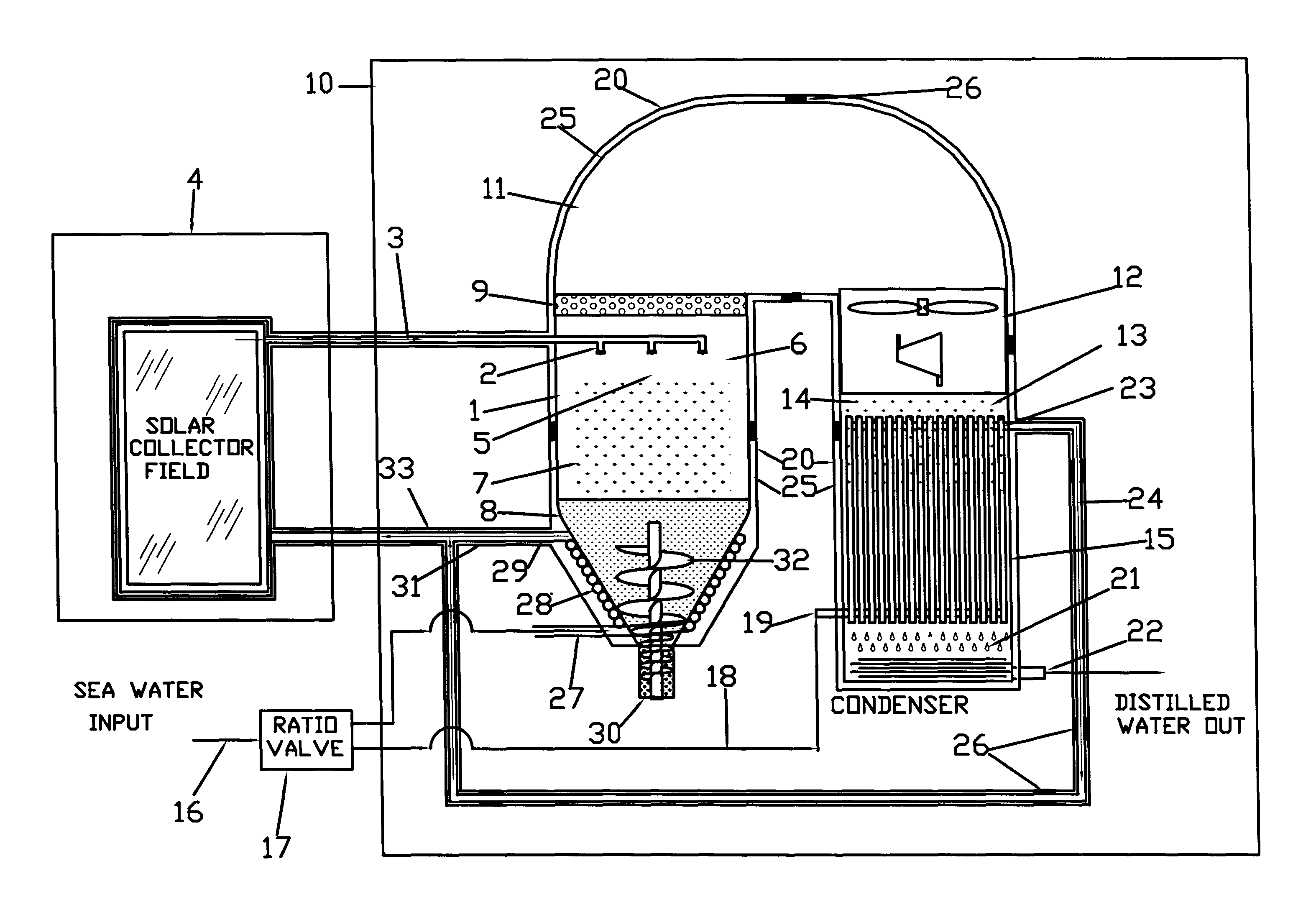
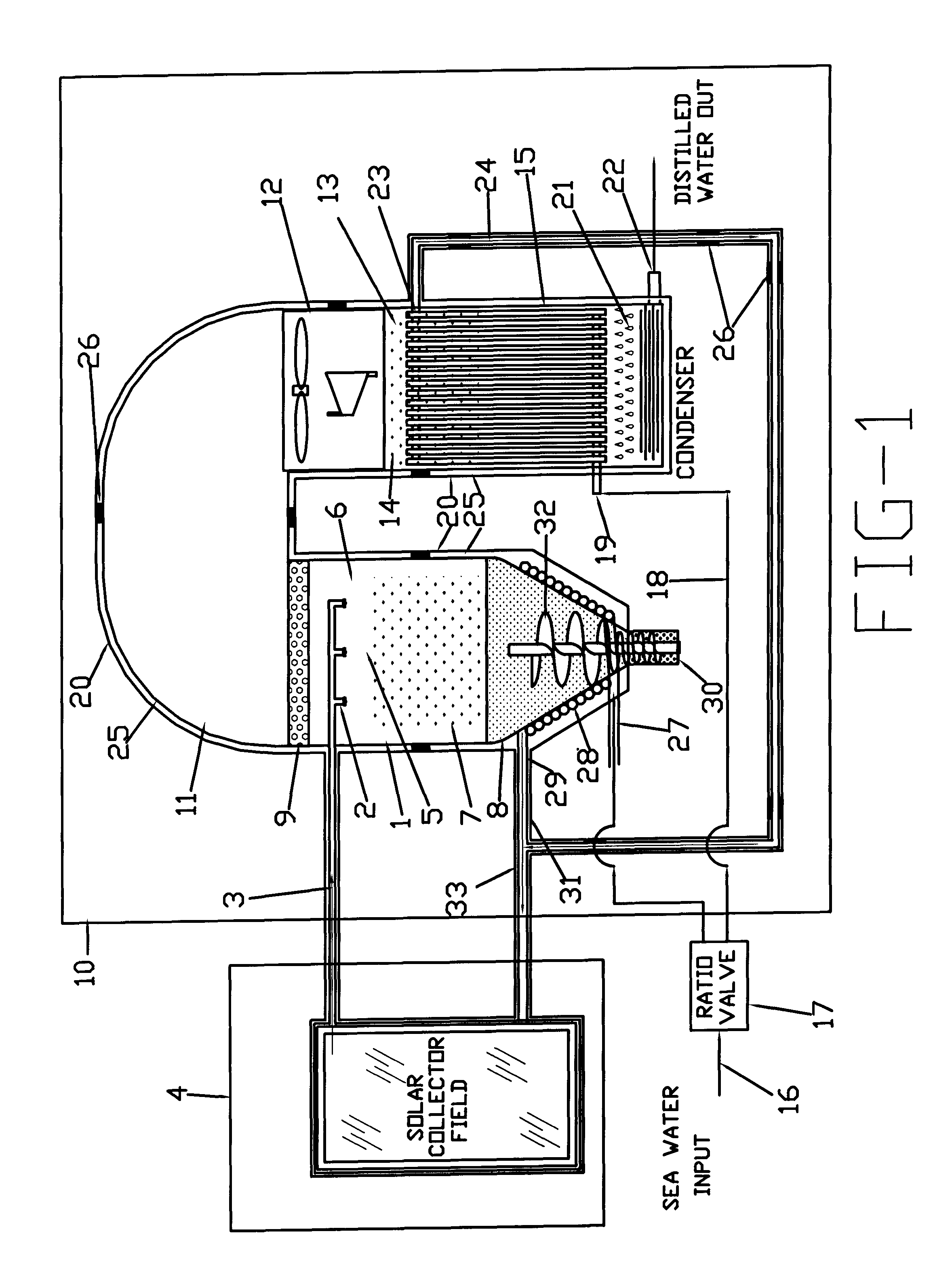
[0083]Referring to the drawings, FIG. 1 is a representative view of the preferred embodiment of the desalination system 10 showing all of the basic assemblies and plumbing surrounded by a secondary wall 20. The space 25 between the assemblies and the secondary wall 20 is under low partial vacuum, between 0.001 and 1 Torr (0.1333 to 133.3 pascal), thereby maintaining very low conductive and convection heat loss. The space 25 can be partially or totally filled with an insulation material 26 for structural support. Perlite is used for the structural support in the preferred embodiments as it exhibits a thermal conductivity of 0.031 W / m*K that improves to 0.00137 W / m*K under partial vacuum.

[0084]Still referring to FIG. 1, the assemblies include an evaporation chamber 1 that houses a plurality of spray nozzles 2 being fed heated input sea water 3 from an external water heater source 4. The preferred external water heater source 4 comprises a solar collector 34 (see FIG. 3), although foss...


PUM

PropertyMeasurementUnit
temperatureaaaaaaaaaa
operating temperaturesaaaaaaaaaa

Abstract

An apparatus and method for the distillation of ocean and brackish water that includes insulation for preventing heat from escaping to the atmosphere is disclosed. The insulation comprises a second wall surrounding the basic assemblies of a desalination system in which the space between the second wall and basic assemblies is under low partial vacuum and is partially or totally filled with an insulation material for structural support. The system allows for flash evaporation of heated input water and condensing the resultant vapors into pure distilled water. The heat of condensation as well as heat from the salt byproduct may be recaptured and used to preheat the input contaminated water.

Description

CROSS-REFERENCE TO RELATED APPLICATION[0001]Not ApplicableFEDERALLY SPONSORED RESEARCH[0002]Not ApplicableSEQUENCE LISTING OR PROGRAM[0003]Not ApplicableSTATEMENT REGARDING COPYRIGHTED MATERIAL[0004]Portions of the disclosure of this patent document contain material that is subject to copyright protection. The copyright owner has no objection to the facsimile reproduction by anyone of the patent document or the patent disclosure as it appears in the Patent and Trademark Office file or records, but otherwise reserves all copyright rights whatsoever.BACKGROUND[0005]The present invention relates primarily to methods of improving the efficiency, and reducing operational and capital costs, of desalination systems. More particularly, to desalination systems that distill brackish or ocean water.[0006]Fresh water is a scant 2.5% of the total global water supply and 69% of that is represented by permanent snow glaciers. The remaining 97.5% is salt water. Since 1940, the amount of fresh water...

Claims


Application Information

Patent Timeline
Patent Type & Authority Patents(United States)
IPC IPC(8): C02F1/06B01D5/00C02F1/12B01D1/18B01D1/00C02F1/14C02F103/08
CPCB01D1/0035B01D1/0094B01D1/18B01D5/006C02F1/12C02F1/14C02F1/06C02F2103/08Y02A20/124Y02A20/142Y02A20/212
Inventor HAYNES, JOEL
Owner FLO ONICS LLC
Why Eureka
Try Eureka