
Catalytic filter having a soot catalyst and an SCR catalyst

a catalytic filter and catalyst technology, applied in the field of catalytic filters, can solve the problems of difficult to efficiently convert into more benign substances, difficult to reduce the back pressure across the filter, and relatively high emissions of exhaust gas particulate matter, so as to reduce the complexity, size and cost of the exhaust gas treatment system, and reduce the effect of soot combustion temperatur

Active Publication Date: 2017-12-26
JOHNSON MATTHEY PLC
View PDF24 Cites 9 Cited by
  • Summary
  • Abstract
  • Description
  • Claims
  • Application Information

AI Technical Summary

Benefits of technology

The present invention is about a new catalytic filter that can reduce soot combustion temperatures without affecting the SCR reaction. This is achieved by combining a soot oxidation catalyst with an SCR catalyst on the filter. This results in a reduction in the complexity, size, and cost of the exhaust gas treatment system. Additionally, the soot oxidation catalyst does not consume nitrogen-based reductants that are required for the downstream SCR reaction. This allows for the dosage of reductants into the exhaust gas upstream of the filter containing the soot oxidation catalyst.

Problems solved by technology

Such lean burn conditions often result in an exhaust gas with relatively high emissions of particulate matter and NOx—two components which have proved to be difficult to efficiently convert into more benign substances.
While this process can be effective in removal of the particles, the accumulation of soot particles on or in the filter can cause an undesirable increase in the back pressure across the filter.
This increase in back pressure typically leads to decreased engine performance and efficiency.
However, removal of the soot oxidation catalyst in an SCRF requires the soot accumulated at the filter surface to be burned at very high temperatures.

Method used


Image

  • Catalytic filter having a soot catalyst and an SCR catalyst
  • Catalytic filter having a soot catalyst and an SCR catalyst

Examples


example 1

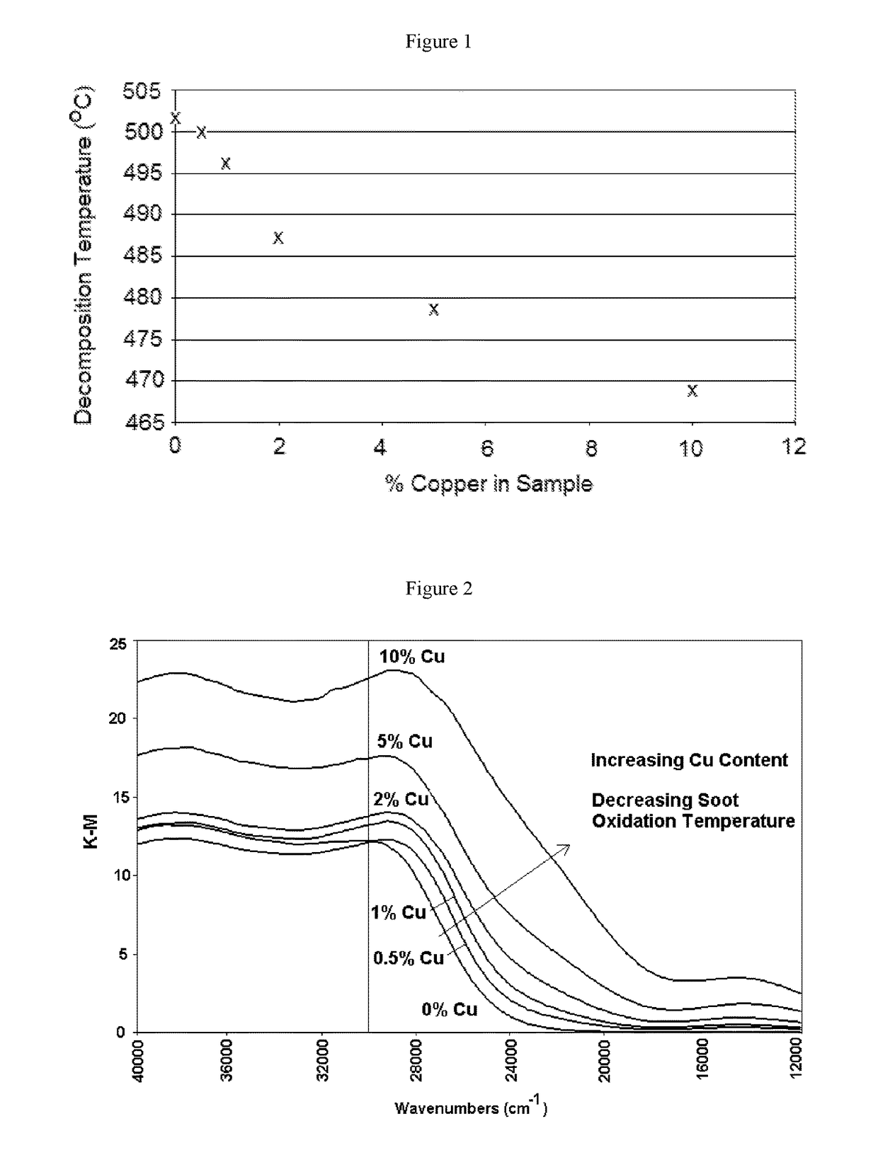
[0104]Samples 1-6 were prepared by applying a washcoat comprising CeZr and various amounts of Cu onto the surface of an inert substrate as shown below. Sample 7 was prepared by applying a washcoat comprising CeZr and 5 wt % Fe onto the surface of an inert substrate. Samples 2-8 did not contain a zeolite. The samples were dried, and then calcined at 500° C. for 1 hour.

[0105]

Cu LoadingOn SootSampleZeoliteSoot CatalystCatalyst1NoneCeZr  0%2CeZr—Cu0.5%3CeZr—Cu  1%4CeZr—Cu  2%5CeZr—Cu  5%6CeZr—Cu 10%7CeZr—Fe  5%

[0106]Each of the samples had about 10% soot added onto the surface of the catalyst.

[0107]The samples were analysed by thermogravimetric analysis (TGA) on a TA Q600 TGA to determine the soot combustion properties starting at a temperature of about 20° C. using a temperature ramp of 20° C. / min to 600° C. in flowing air at 80 ml / min at 20 ml / min to determine the amount of soot that was combusted. Samples 1-6 were also analysed by UV / Visible spectroscopy using a Perkin Elmer Lambda 6...

example 2

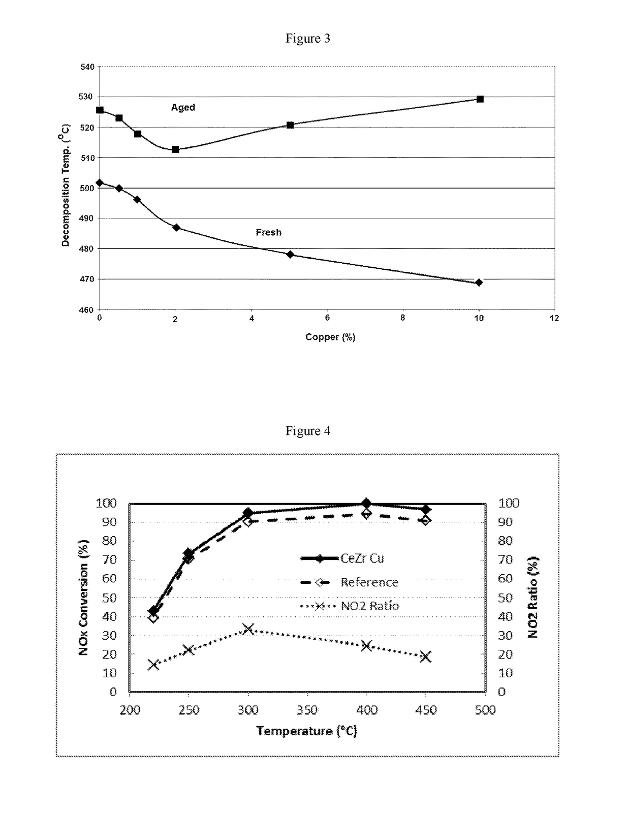
[0112]Samples from Example 1 were aged at 800° C. for 16 hours. The samples were analysed by thermogravimetric analysis (TGA) and UV / visible spectroscopy as described in in Example 1.

[0113]The table below shows the effect of copper loading on the peak oxidation temperature of the soot catalyst in aged soot catalyst. CeZr with a 2% Cu loading exhibited the lowest peak soot oxidation temperature.

[0114]

PeakOxidation TempSample(° C.)8Aged CeZr 0% Cu5269Aged CeZr 0.5% Cu52310Aged CeZr 1% Cu51811Aged CeZr 2% Cu51312Aged CeZr 5% Cu52113Aged CeZr 10% Cu52914Aged CeZr 5% Fe555

[0115]All aged samples containing Cu in any amount were more effective at reducing the oxidation temperature than aged samples comprising 5% Fe. Aged samples containing 0.5-5% Cu were more effective at reducing the oxidation temperature than aged samples comprising 0% Cu.

[0116]FIG. 3 demonstrates that there are differences in the catalytic activity between fresh and aged samples and 2% and 10% copper loadings provide th...

example 3

[0118]The ability of fresh and hydrothermally aged catalyst was evaluated on an engine bench test under passive (engine at 3000 rpm with catalyst at 490° C.) and active (exhaust flow of 100 kg / hr with catalyst at 630° C. for 12 minutes) conditions.

[0119]A reference catalyst comprised Cu-CHA at a loading of 0.81 g / in3. A catalyst of the invention comprised Cu-CHA at a loading of 0.81 g / in3 and CeZr+Cu (2 wt %) at a loading of 0.1 g / in3. FIG. 4 shows the % NOx conversion at temperatures from about 225° C. to about 450° C. The catalyst comprising both Cu-CHA and CeZr—Cu (2 wt %) provided higher NOx conversion than the reference sample that did not contain CeZr—Cu. The NO2: NOx ratio was between about 15% and about 35% over this temperature range. These results demonstrate that the presence of the required soot catalyst in a mixture with an SCR catalyst does not have a negative impact on the performance of the SCR catalyst.

[0120]The regeneration efficiency of the catalyst determined und...


PUM

PropertyMeasurementUnit
temperatureaaaaaaaaaa
molar ratioaaaaaaaaaa

Abstract

A catalytic filter is provided having a mixture of an SCR catalyst and soot oxidation catalyst where the soot oxidation catalyst is a copper doped ceria, iron doped ceria or manganese doped ceria. The mixture of an SCR catalyst and soot oxidation catalyst provides for a lowering of the peak oxidation temperature for soot removal from the filter. The use of the filter allows for improved soot combustion and reduces the susceptibility of an SCR catalyst contained on a filter to deterioration. The soot oxidation catalyst also improves the resistance of the SCR catalyst to poisoning and subsequent deterioration of SCR performance.

Description

CROSS-REFERENCE TO RELATED APPLICATIONS[0001]This application claims priority to U.S. Provisional Application No. 62 / 234,123, filed Sep. 29, 2015, which is incorporated herein by reference.FIELD OF THE INVENTION[0002]The present invention relates to catalysts, systems, and methods that are useful for treating an exhaust gas that is produced during combustion of hydrocarbon fuel, particularly a lean burn exhaust gas containing soot and nitrogen oxides produced by a diesel engine.BACKGROUND[0003]Exhaust gas is generated during the combustion of fuels such as natural gas, gasoline, diesel fuel, fuel oil or coal. When the combustion occurs in a chamber such as an engine or furnace, the resulting exhaust gas is typically treated prior to being discharged into the atmosphere through an exhaust pipe, flue gas stack or the like. Although the largest portion of exhaust gas consists of nitrogen (N2), water vapor (H2O), and carbon dioxide (CO2), which are considered to be innocuous compounds, ...

Claims


Application Information

Patent Timeline
Patent Type & Authority Patents(United States)
IPC IPC(8): F01N3/033B01J23/72B01J23/745B01J29/76B01J23/83B01J35/04B01J23/34F01N3/035B01D53/94B01J23/10B01D46/00
CPCB01J35/04B01D53/9418B01J23/83B01J29/763B01D2255/915B01D2255/2065B01D2255/20715B01D2255/20761B01D53/9431B01D53/944F01N3/035B01D2255/2066B01D2255/2068B01D2255/2073B01D2255/20738B01D2258/012B01J37/0246B01J37/10B01J23/002B01J23/34B01J37/0215F01N3/2066B01J2523/00F01N2370/02Y02T10/12Y02A50/2351B01J35/56B01J2523/17B01J2523/3712B01J2523/48B01J2523/842B01J23/10B01J23/54B01J29/00B01J29/064F01N3/20B01D53/94
Inventor CHANDLER, GUY RICHARDPHILLIPS, PAUL RICHARD
Owner JOHNSON MATTHEY PLC
Learn More