Vertical skein of hollow fiber membranes and method of maintaining clean fiber surfaces while filtering a substrate to withdraw a permeate

Inactive Publication Date: 2002-02-19
ZENON TECH PARTNERSHIP
View PDF10 Cites 180 Cited by
  • Summary
  • Abstract
  • Description
  • Claims
  • Application Information

AI Technical Summary

Benefits of technology

It has been discovered that bubbles of a fiber-cleansing gas ("scrubbing gas") flowing parallel to fibers in a vertical skein are more effective than bubbles which are intercepted by arcuate fibers crossing the path of the rising bubbles. Bubbles of an oxygen-containing gas to promote growth of microbes unexpectedly fails to build-up growth of microbes on the surfaces of the fibers because the surfaces are "vertically air-scrubbed". Deposits of animate a

Problems solved by technology

Bubbles of an oxygen-containing gas to promote growth of microbes unexpectedly fails to build-up g

Method used


Image

  • Vertical skein of hollow fiber membranes and method of maintaining clean fiber surfaces while filtering a substrate to withdraw a permeate
  • Vertical skein of hollow fiber membranes and method of maintaining clean fiber surfaces while filtering a substrate to withdraw a permeate
  • Vertical skein of hollow fiber membranes and method of maintaining clean fiber surfaces while filtering a substrate to withdraw a permeate

Examples


example

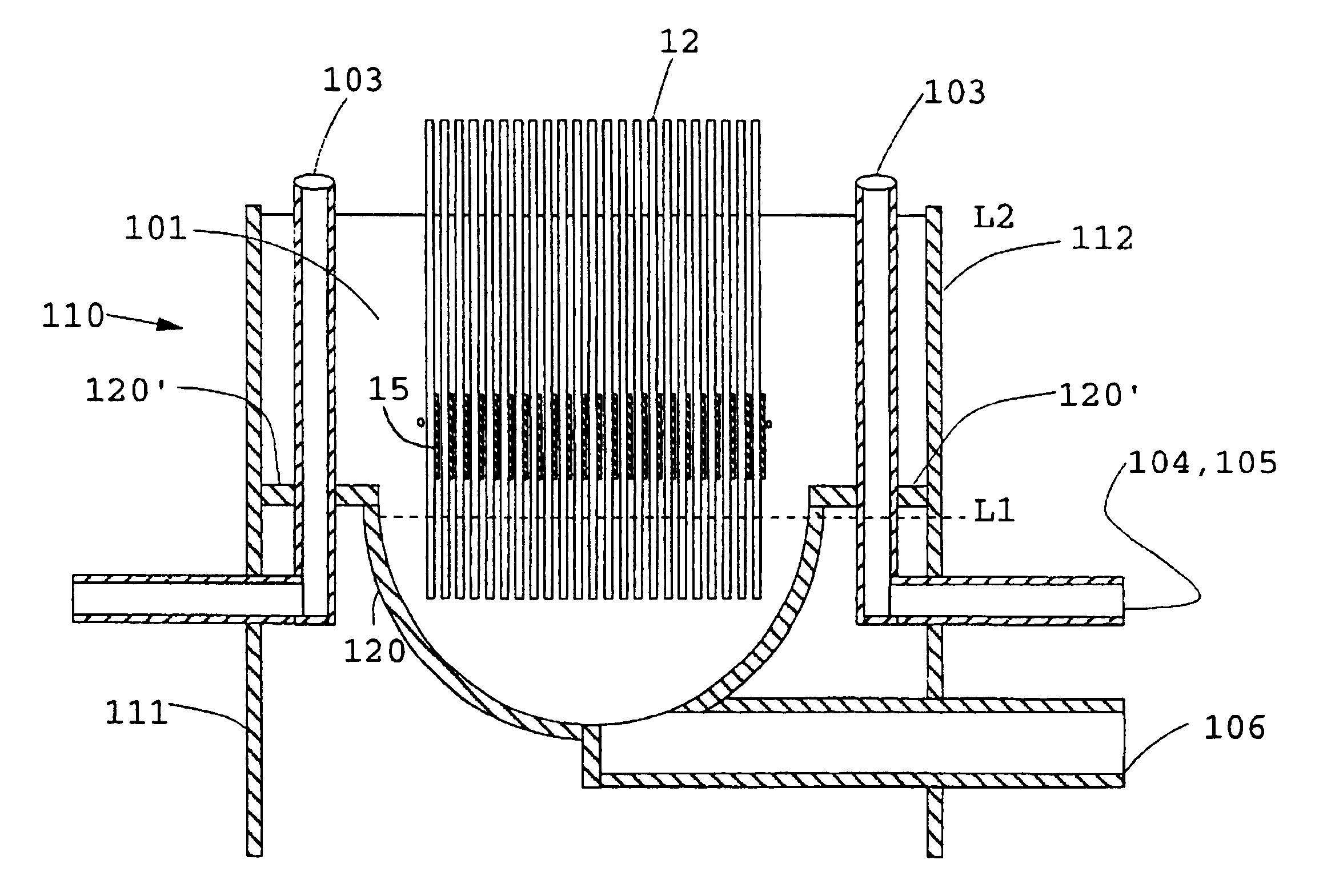
Microfiltration of an activated sludge at 30.degree. C. having a concentration of 25 g / L (2.5% TSS) is carried out with a skein of polysulfone fibers in a pilot plant tank. The fibers are "air scrubbed" at a flow rate of 12 CFM (0.34 m.sup.3 / min) with a coarse bubble diffuser generating bubbles in the range from about 5 mm to 25 mm, in nominal diameter. The air is sufficient not only for the oxidation requirements of the biomass but also for adequate scrubbing. The fibers have an outside diameter of 1.7 mm, a wall thickness of about 0.5 mm, and a surface porosity in the range from about 20% to 40% with pores about 0.2 .mu.m in diameter, both latter physical properties being determined by a molecular weight cut off at 200,000 Daltons. The skein which has 1440 fibers with a surface area of 12 m.sup.2, is wall-mounted in the tank, the vertical spaced apart distance of the headers being about 1% less than the length of a fiber in the skein. The opposed ends of the fibers are potted in ...


PUM

PropertyMeasurementUnit
Lengthaaaaaaaaaa
Lengthaaaaaaaaaa
Lengthaaaaaaaaaa

Abstract

A vertical skein of "fibers", opposed terminal portions of which are held in headers unconfined in a modular shell, is aerated with a gas-distribution means which produces a mass of bubbles serving the function of a scrub-brash for the outer surfaces of the fibers. The membrane device is surprisingly effective with relatively little cleansing gas, the specific flux through the membranes reaching an essentially constant relatively high value because the vertical deployment of fibers allows bubbles to rise upwards along the outer surfaces of the fibers. Further, bubbles flowing along the outer surfaces of the fibers make the fibers surprisingly resistant to being fouled by build-up of deposits of inanimate particles or microorganisms in the substrate provided that the length of each fiber is only slightly greater than the direct center-to-center distance between opposed faces of the headers, preferably in the range from at least 0.1% to about 5% greater. For use in a large reservoir, a bank of skeins is used with a gas distributor means and each skein has fibers preferably >0.5 meter long, which together provide a surface area >10 m2. The terminal end portions of fibers in each header are kept free from fiber-to-fiber contact with a novel method of potting fibers.

Description

BACKGROUND OF THE INVENTIONThis invention relates to a membrane device which is an improvement on a frameless array of hollow fiber membranes and a method of maintaining clean fiber surfaces while filtering a substrate to withdraw a permeate, which is also the subject of U.S. Pat. No. 5,248,424; and, to a method of forming a header for a skein of fibers. The term "vertical skein" in the title (hereafter "skein" for brevity), specifically refers to an integrated combination of structural elements including (i) a multiplicity of vertical fibers of substantially equal length; (ii) a pair of headers in each of which are potted the opposed terminal portions of the fibers so as to leave their ends open; and, (iii) permeate collection means held peripherally in fluid-tight engagement with each header so as to collect permeate from the ends of the fibers.The term "fibers" is used for brevity, to refer to "hollow fiber membranes" of porous or semipermeable material in the form of a capillary...

Claims


Application Information

Patent Timeline
IPC IPC(8): B01D63/02B01D61/18B01D63/04B01D65/08B01D65/02B01D65/00C02F1/44B01D61/20
CPCB01D61/18B01D63/02B01D63/021B01D63/022B01D63/023B01D63/026B01D63/043B01D65/02B01D65/08B01D69/02B01D61/20C02F1/444B01D2313/26B01D2315/06B01D2321/04B01D2321/185B01D2321/2066B01D63/027C02F3/1273B01D2321/12Y10S264/48Y02W10/10
Inventor MAHENDRAN, MAILVAGANAMRODRIGUES, CARLOS FERNANDO F.PEDERSEN, STEVEN KRISTIAN
Owner ZENON TECH PARTNERSHIP
Why Eureka
Try Eureka