Making method of micro-electro-mechanical V-type micro valve

A technology of microelectronic machinery and manufacturing methods, which is applied in the field of actuators, can solve problems such as high processing accuracy requirements, difficult processes, and complex structures, and achieve the effects of reducing processing accuracy requirements, simple manufacturing processes, and small volume

Inactive Publication Date: 2008-08-06
HEILONGJIANG UNIV
View PDF4 Cites 0 Cited by
  • Summary
  • Abstract
  • Description
  • Claims
  • Application Information

AI Technical Summary

Problems solved by technology

The disadvantage is that the structure is complex, the p

Method used


Image

  • Making method of micro-electro-mechanical V-type micro valve
  • Making method of micro-electro-mechanical V-type micro valve
  • Making method of micro-electro-mechanical V-type micro valve

Examples


Embodiment 1

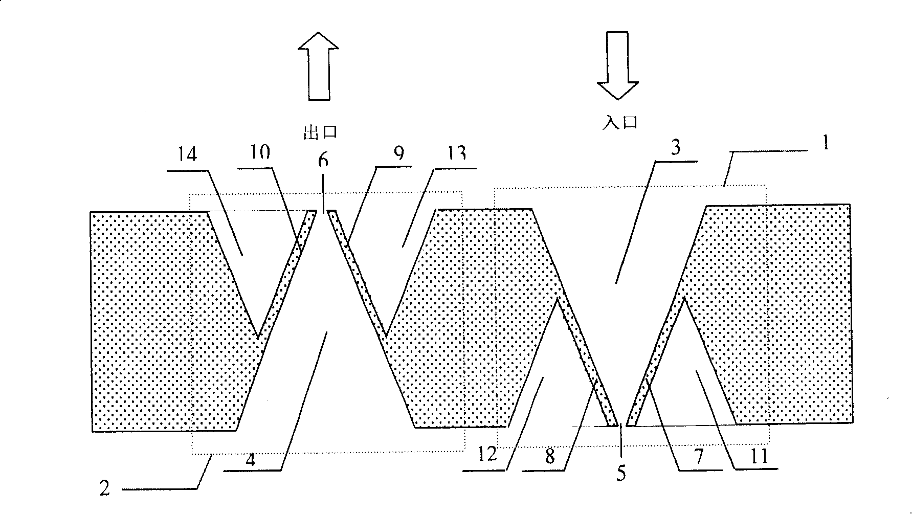
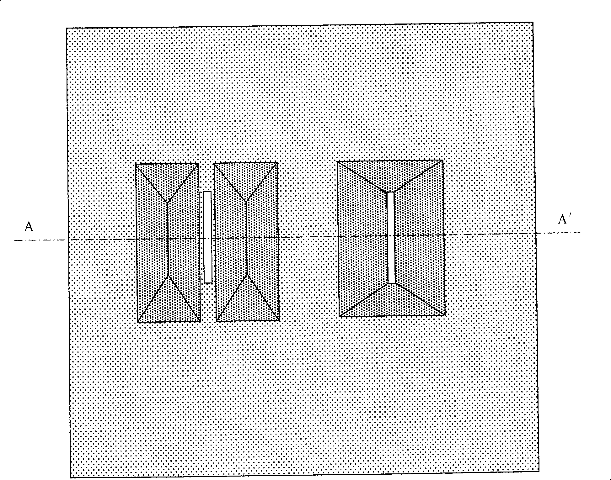
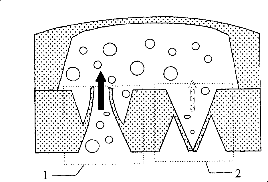
[0023] Micro-electromechanical V-type microvalve, which consists of: positive one-way valve [1] and reverse one-way valve [2] placed symmetrically and oppositely to the structure of the positive one-way valve, the positive one-way valve [2] The entire structure of the valve and the reverse one-way valve are formed on the silicon substrate, and the positive one-way valve [1] includes the water inlet [3], the water inlet seam [5], the valve plate [7] / [8] and two V type groove [11] / [12]; anti-check valve [2] includes water outlet [4], water outlet seam [6], valve plate [9] / [10] and two V-shaped grooves [13] / [ 14] (see attached figure 1 ).

[0024] For the above-mentioned V-shaped microvalve of micro-electronic machinery, the angle between the release valve plates on both sides and the angle of the V-shaped groove is the included angle of the anisotropic etching of crystal to silicon, and the optimal angle is 54°44′20 ", the thickness of the valve plate is half of the value obta...

Embodiment 2

[0031] The manufacturing method of the V-type microvalve of the microelectronic machinery described in embodiment 1, selects the double-sided polishing P-type (100) silicon chip thickness to be 330 μ m~550 μ m, double-sided oxidation 400nm, low-temperature plasma chemical vapor deposition, double-sided growth Si 3 N 4 200nm, double-sided photolithography window, etched with KOH aqueous solution for 1-2 hours, cooled at 40°C for over-etching until breakthrough, the etching time depends on the time required to engrave the thickness of the silicon substrate material, the etching height is the thickness of the silicon wafer, Go to Si after piercing 3 N 4 Protective layer, and finally use HF solution to remove the oxide layer.

[0032]The manufacturing method of the V-shaped microvalve of the above-mentioned microelectronic machinery, the water inlet seam, the water outlet seam, and the valve plate are all made of silicon micromachining, and are prepared after being corroded by ...


PUM

PropertyMeasurementUnit
Thicknessaaaaaaaaaa

Abstract

The invention relates to a V-shape micro-valve of micro-electronic mechanics and relative producing method, while its property directly affects the property of micro-pump. The invention comprises: a positive one-way valve (1) and a reverse one-way valve (2) arranged reversely to the positive one-way valve. Wherein, the structures of said two valves are formed on the silicon base, while the positive one-way valve (1) comprises a water inlet (3), a water inlet slit (5), valve plates (7) and (8) and two V-shape grooves (11) and (12); and the reverse one-way valve comprises a water outlet (4), a water outlet slit (6), valve plates (9) and (10) and two V-shape grooves (13) and (14). The invention can be used in medicine micro-transmission, fuel micro-injection, ink injection printing and micro-chemical analysis, especially cooling high power elements and grand scale integration. It can be used in the accurate control in future micro-liquid control system as chemical vapor deposition and molecule beam extension, and cooling low-temperature superconductor and the micro chemical analysis of gas and liquid.

Description

Technical field: [0001] The invention relates to a structure and a manufacturing method of a V-shaped valved microvalve based on microelectromechanical technology, which belongs to actuators in the field of microfluidic systems. Background technique: [0002] The existing micro-mechanical system (MEMS) has developed rapidly as a new field in recent years. Micro-fluidic system is an important branch of micro-mechanical system, which is mainly used for micro-chemical analysis and micro-injection of drugs. Microvalve is an important executive component of flow direction control in microfluidic system, and its performance has a direct impact on the performance index of micropump. Micro-valve can be divided into valve-type and non-valve-type structure, micro-valve and micro-drive together to form a micro-pump. With the gradual maturity of micromachining technology, many valved microvalves with different structures and materials have been successfully fabricated so far. The firs...

Claims


Application Information

Patent Timeline
IPC IPC(8): F04B43/02F15C5/00F16K13/00H01L21/00H01L49/00
Inventor 邱成军曹茂盛张辉军曲伟孟丽娜
Owner HEILONGJIANG UNIV
Why Eureka
Try Eureka