
Manufacturing method of plate type oxygen sensor chip

A technology of oxygen sensor and manufacturing method, which is applied in the direction of instruments, scientific instruments, measuring devices, etc., can solve the problems of easy deformation of sintering, poor compactness, poor performance, etc., achieve smooth and smooth substrate quality, solve lamination and sealing, and improve The effect of product qualification rate

Inactive Publication Date: 2009-05-13
ZHENJIANG NERNST AUTOMOTIVE TECH
View PDF9 Cites 0 Cited by
  • Summary
  • Abstract
  • Description
  • Claims
  • Application Information

AI Technical Summary

Problems solved by technology

[0009] The disadvantages of this method are: the blank is too brittle, the yield is low, the sintering is easy to deform, the sealing is difficult, and its shock resistance and thermal shock resistance are very poor, so it is a kind of manufacturing with high cost and poor performance. method
[0011] The disadvantages of this method are: rolling film forming is easy to introduce impurities, and at the same time, the stress of the formed substrate is relatively large, the thickness uniformity is poor, there are more bubbles, and the compactness is poor
In addition, punching blanks on the punching machine is also easy to introduce new stresses, which will increase the probability of final sintering deformation, difficult sealing, and low yield

Method used

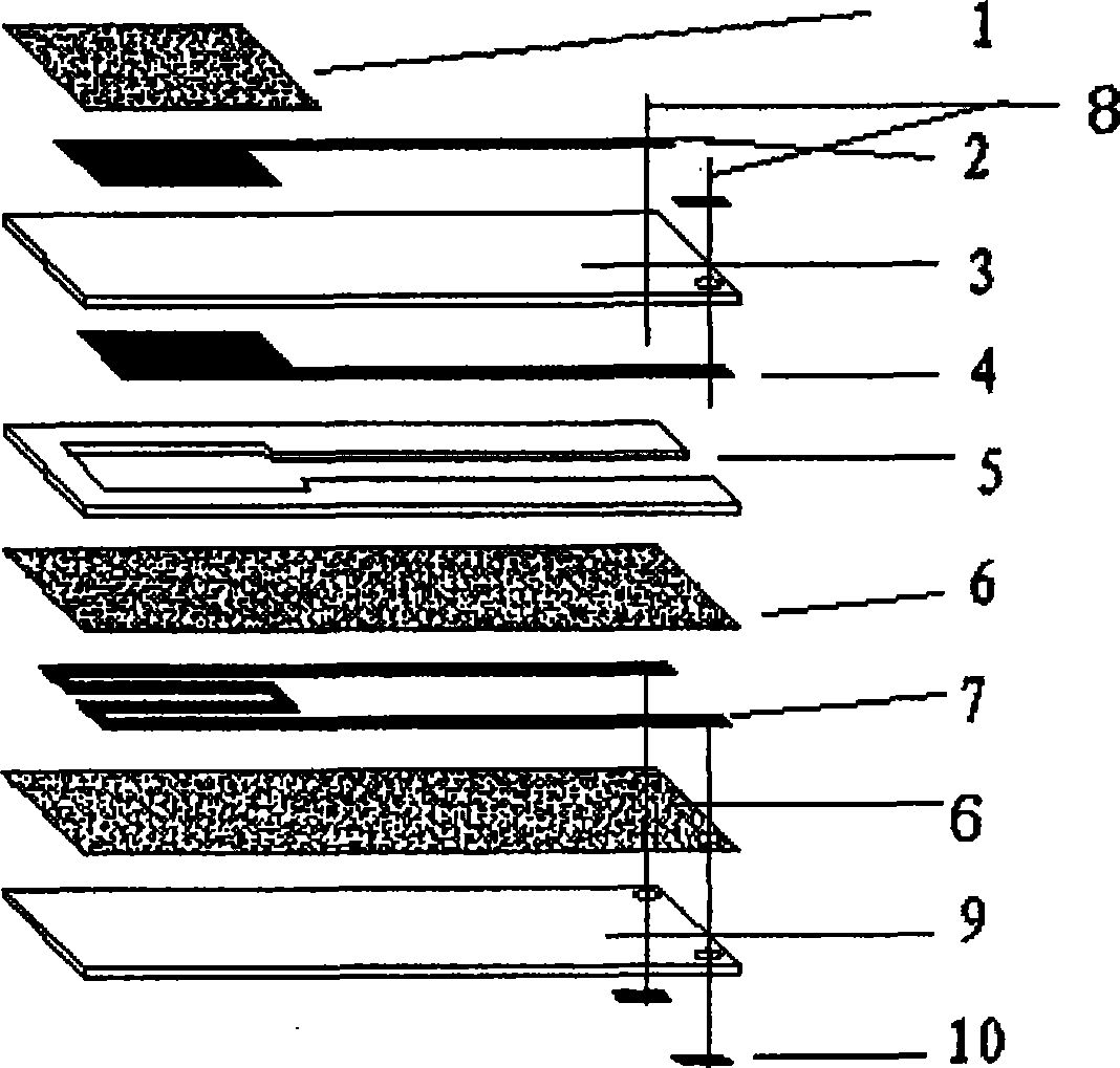
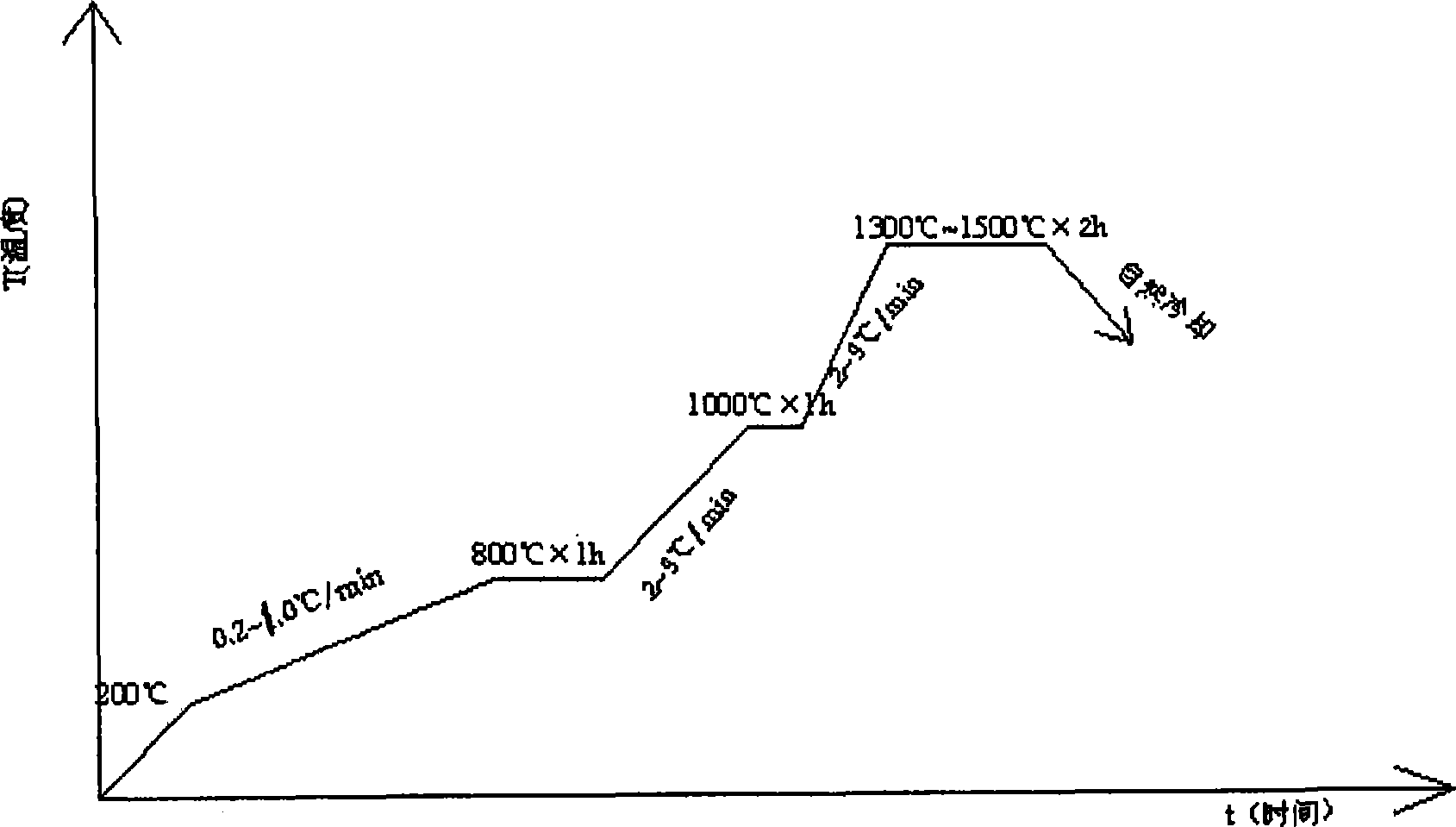

Image

  • Manufacturing method of plate type oxygen sensor chip
  • Manufacturing method of plate type oxygen sensor chip
  • Manufacturing method of plate type oxygen sensor chip

Examples


Embodiment 1

[0029] 1. Prepare cast slurry: Put 200 grams of yttrium-doped zirconia powder as the base material for the sensor sheet, intermediate sheet and heating sheet into a ball mill jar, first add 120 ml of ethanol for ball milling, and then add 14 grams of polyethylene Alcohol butyral is used as a binder, continue ball milling, and when the mixture reaches a viscosity of 500-4000mPa.s, it becomes a casting slurry;

[0030] 2. Casting: The casting slurry prepared in the first step is scraped on the casting machine with a scraper on the backing belt to form a film with uniform thickness. The thickness of the casting is adjusted by the height of the scraper, the speed of the tape and the viscosity of the slurry. Control, the height of the scraper is adjusted by the micrometer placed on the scraper frame, the drying speed of the film is affected by the temperature and the organic solvent content in the film, generally it is dried at room temperature, and it can be controlled at 30°C in w...

Embodiment 2

[0037] 1. Preparation of casting slurry: Put 200 grams of yttrium-doped zirconia powder as the base material for the sensor sheet, intermediate sheet and heating sheet into a ball mill tank, first add 120 ml of xylene and 3 g of triethanolamine for dispersion Agent ball milling, then add 16 grams of polyvinyl alcohol as binding agent;

[0038] All the other steps are the same as in Example 1.

Embodiment 3

[0040] 1. Preparation of casting slurry: Put 200 grams of yttrium-doped zirconia powder as the base material for the sensor sheet, intermediate sheet and heating sheet into a ball milling tank, first add 120 ml of toluene and 3 grams of fish oil as a dispersant for ball milling , then add 10 grams of ethyl cellulose as a binder, add 5 grams of butyl benzyl phthalate and 5 grams of polyethylene glycol as plasticizers and lubricants to continue ball milling, when the mixture reaches 500 ~ 4000mPa.s Viscosity, that is cast slurry;

[0041] All the other steps are the same as in Example 1.


PUM


Abstract

This invention relates to one process method to control cargo motor hollow burst plane oxygen sensor chip, which comprises the following steps: processing flow paste on zircite ceramics powder mixed with yttrium and processing bright and complete film through flow and then cutting into relative sensor slices, heating slice and middle slices by non-contact cut machine; printing electrode inside sensor slice and heating resistance on heating slices; then using overlap heating type to integrate three slices into plane sensor load to remove organism under temperature of 1300 to 1500 degrees.

Description

technical field [0001] The present invention relates to a manufacturing method of an oxygen sensor, in particular to a manufacturing method of a flat oxygen sensor chip. The flat oxygen sensor is applied to an automobile engine system and controls the air-fuel ratio by detecting the oxygen content of the exhaust gas in feedback so as to reduce exhaust emissions . Background technique [0002] The environmental pollution caused by automobile exhaust emissions is the main source of air pollution. Countries around the world are paying more and more attention to this, and the emission standards are getting higher and higher. The main measure to reduce automobile exhaust pollution is to use oxygen sensors to detect the oxygen content of exhaust gases. To control the air-fuel ratio of the engine, the exhaust gas generated by the engine can be efficiently converted into harmless gas through the three-way catalytic converter near the theoretical air-fuel ratio (14.6±0.2), reducing p...

Claims


Application Information

Patent Timeline
Patent Type & Authority Patents(China)
IPC IPC(8): G01N27/407G01N27/12
Inventor 谢光远
Owner ZHENJIANG NERNST AUTOMOTIVE TECH
Learn More