Method for producing conductive pattern material

A manufacturing method and conductivity technology, which can be applied in conductive pattern formation, printed circuit manufacturing, cable/conductor manufacturing, etc., can solve the problems of graft polymer and metal peeling, etc., and achieve excellent retention of conductive materials and longevity Excellent performance and high resolution

Inactive Publication Date: 2007-09-12
FUJIFILM CORP
View PDF6 Cites 10 Cited by
  • Summary
  • Abstract
  • Description
  • Claims
  • Application Information

AI Technical Summary

Problems solved by technology

However, in this technology, there is a problem that large-scale processing such as plasma treatment must be performed
[0007] When the graft polymer is bonded to the surface of the substrate, sufficient adhesion between the substrate and the metal is obtained, but under conditions such as high humidity, the problem of peeling of the graft polymer from the metal occurs.

Method used


Image

  • Method for producing conductive pattern material
  • Method for producing conductive pattern material
  • Method for producing conductive pattern material

Examples


Embodiment 1

[0224] [(1) Graft polymer pattern forming process]

[0225] Using PET (188m, manufactured by Toray Co., Ltd.) as a substrate, the photopolymerizable composition described below was coated on the surface with a No. 18 coating bar, and dried at 80° C. for 2 minutes to form an intermediate layer with a thickness of 6 μm.

[0226]

[0227] ·Allyl methacrylate / methacrylic acid copolymer 2g

[0228] (The molar ratio of copolymerization is 80 / 20, and the average molecular weight is 100,000)

[0229] ·Ethylene oxide modified bisphenol A diacrylate 4g

[0230] ·1-Hydroxycyclohexyl phenyl ketone 1.6g

[0231] ·1-methoxy-2-propanol 16g

[0232] — Generate graft polymer —

[0233] Then, drop 5mL of 5wt% monomer aqueous solution of acrylic acid / glycidyl methacrylate (molar ratio 80 / 20) on the intermediate layer, cover it with a quartz plate, so that the monomer aqueous solution is evenly sandwiched in the intermediate layer and the quartz plate. A patterned light-shielding film (NC-1...

Embodiment 2

[0243] [(1) Graft polymer pattern forming process]

Synthetic example 1

[0244] (Synthesis Example 1: Synthesis of Compound A)

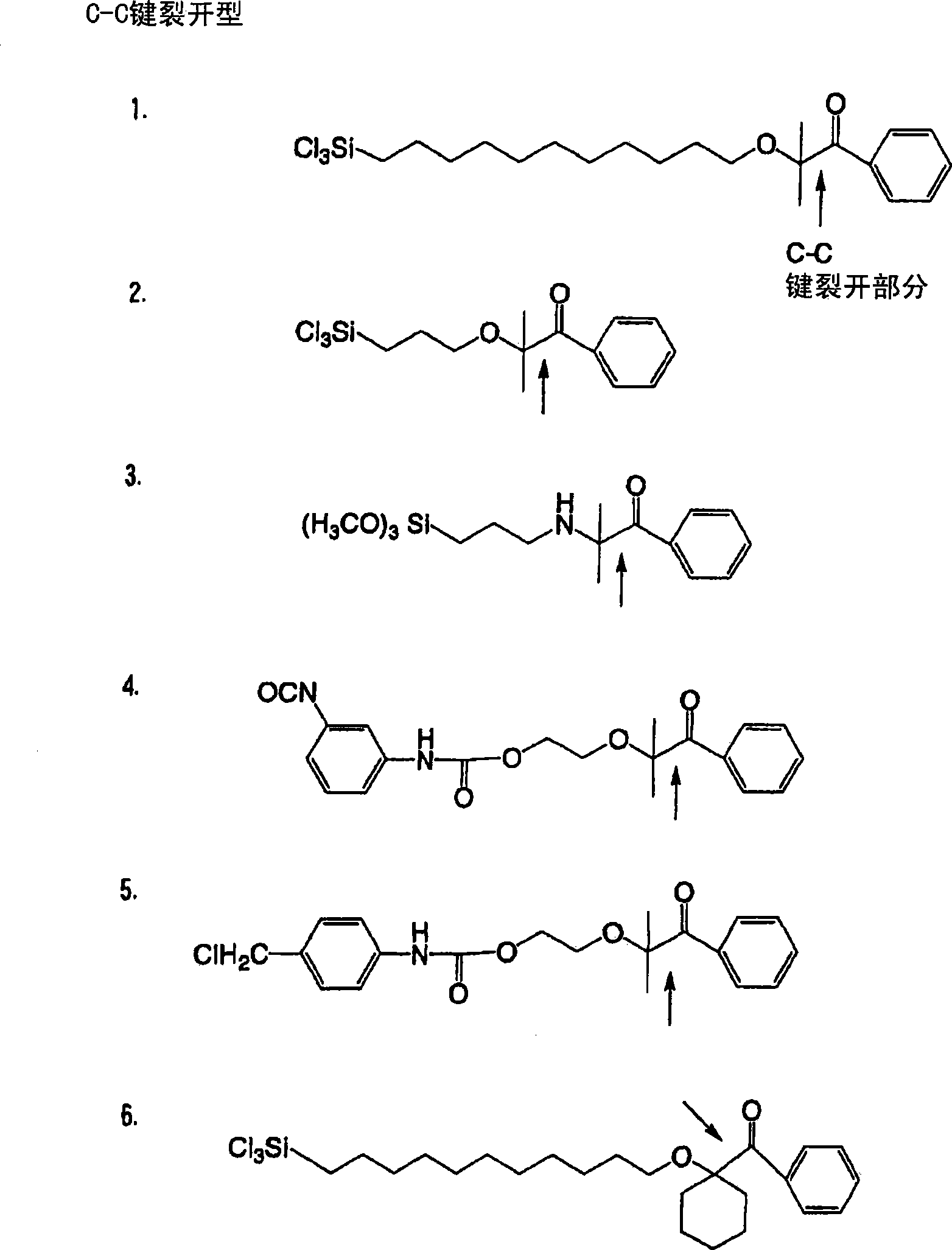
[0245] The synthesis of Compound 1 exemplified above was carried out by the following two steps. Give a schematic diagram of each step to explain.

[0246] 1. Step 1 (synthetic compound a)

[0247] Dissolve 24.5 g (0.12 mol) of 1-hydroxycyclohexyl phenyl ketone in a mixed solvent of 50 g DMAc and 50 g THF, and slowly add 7.2 g (0.18 mol) of NaH (60% oil suspension) in a water bath. Further, 44.2 g (0.18 mol) of 11-bromo-1-undecene (95%) was added dropwise thereto, and the reaction was carried out at room temperature. The reaction was terminated after 1 h. The reaction solution was poured into ice water and extracted with ethyl acetate to obtain a mixture containing Compound a as a yellow solution. 37 g of this mixture were dissolved in 370 mL of acetonitrile, and 7.4 g of water were added. Add 1.85g p-toluenesulfonic acid monohydrate and stir at room temperature for 20min. The organic phase was extracted with ethyl ...


PUM

PropertyMeasurementUnit
particle sizeaaaaaaaaaa

Abstract

A method for manufacturing a conductive pattern material is provided with a process of directly bonding a graft polymer, which has a functional group and a crosslinkable functional group that can mutually interact with conductive particles, on a substrate in a pattern; a process of forming a conductive particle adsorbing layer by permitting the functional group which can mutually interact with conductive particles in the graft polymer to adsorb conductive particles; and a process of forming a crosslinking structure in the conductive particle adsorbing layer by applying energy to the conductive particle adsorbing layer. In this method, a conductive pattern material provided with a conductive pattern which has a high resolution without interruption and has excellent durability can be manufactured. The conductive pattern material can be also obtained by introducing a functional group which can mutually interact with an electroless plating catalyst, instead of the functional group which can mutually interact with conductive particles, and by adsorbing the electroless plating catalyst and the like and performing electroless plating process.

Description

technical field [0001] The present invention relates to a method for producing a conductive pattern material, and more specifically, to a method for producing a conductive pattern material used as a printed wiring board. Background technique [0002] Conventionally, various conductive pattern materials have been used in the manufacture of wiring boards. As a representative of such materials, the general method is to place a conductive material formed by a known method such as vacuum evaporation deposition on an insulator, perform protection treatment on it, remove a part of the protection film previously formed by pattern exposure, and then perform etching treatment. Form the desired pattern. Such a method has at least four complicated steps as necessary steps. In particular, in this method, when wet etching is performed during the etching process, a step of treating the waste liquid is necessary, which is necessary but more complicated. [0003] As another method of form...

Claims


Application Information

Patent Timeline
Patent Type & Authority Applications(China)
IPC IPC(8): H05K3/10G03F7/40B05D5/12C08J7/04H01B13/00
CPCC08F291/00C08F251/02H05K2203/1168H05K3/386G03F7/0047H05K3/102H05K3/185G03F7/405C08F292/00C08F255/00C08F289/00B05D5/12
Inventor 川村浩一加纳丈嘉
Owner FUJIFILM CORP
Why Eureka
Try Eureka