Slurry bubble columun reactor having internal circulation and external heat-exchanging and the application

A slurry bed, internal circulation technology, applied in chemical instruments and methods, chemical/physical processes, etc., can solve the problems of uneven solid suspension, space velocity can not be too large, catalyst sedimentation, etc., to achieve convenient removal of reaction heat, The effect of low energy consumption and high space-time yield

Active Publication Date: 2007-09-19
EAST CHINA UNIV OF SCI & TECH
View PDF4 Cites 30 Cited by
  • Summary
  • Abstract
  • Description
  • Claims
  • Application Information

AI Technical Summary

Problems solved by technology

However, there is a certain limit to the amount of catalyst loaded in this slurry reactor, so the space velocity in operation should not be too large
[0005] At the same time, the bottleneck of the current three-p...

Method used


Image

  • Slurry bubble columun reactor having internal circulation and external heat-exchanging and the application
  • Slurry bubble columun reactor having internal circulation and external heat-exchanging and the application
  • Slurry bubble columun reactor having internal circulation and external heat-exchanging and the application

Examples


Embodiment 1

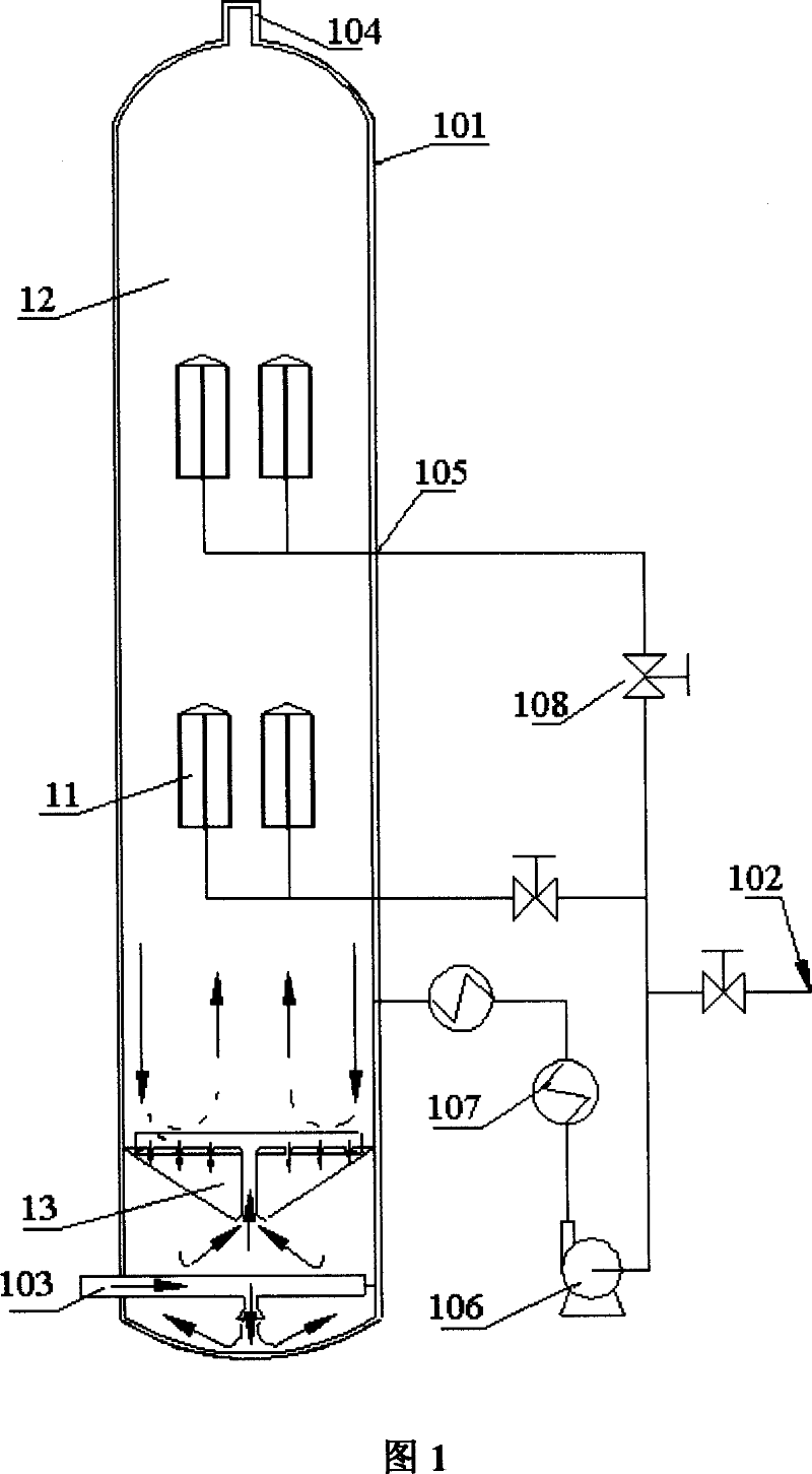
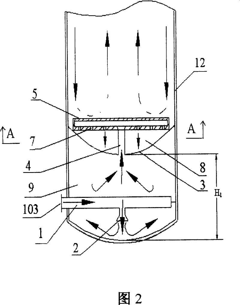
[0049] The reactor shown in Figure 1 and the orifice gas distributor shown in Figure 2 were used.

[0050] The effective diameter of the three-phase slurry bed reactor is 3.2m, the effective height is 10m, the orifice diameter of the orifice gas distributor is 10mm, the gas velocity at the orifice outlet is 180m / s, and there are 3 layers of filters built in.

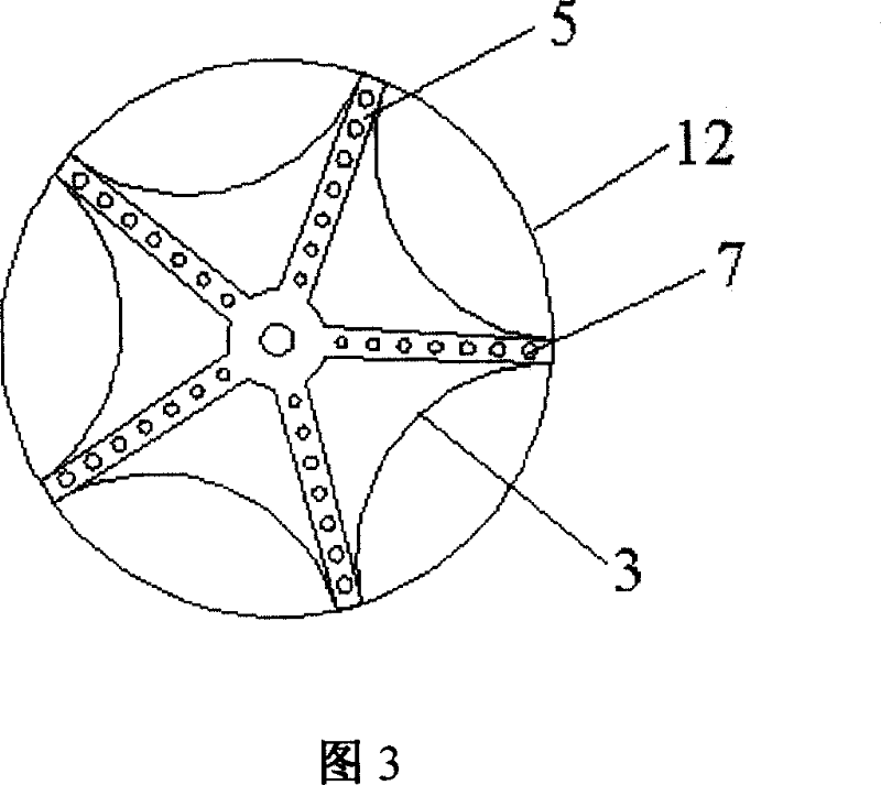
[0051] The diameter of the orifice 7 is 3mm, and the opening ratio is 0.33%;

[0052] The distance H from the bottom of the reactor to the impact plate 3 1 200mm;

[0053] The diameter of the gas inlet pipe 1 is 80 mm; the distance H from the bottom of the reactor to the impact plate 3 1 200mm;

[0054] The shape of the impact bottom plate 3 is arc-shaped, and the arc is 135°;

[0055] The diameter of air guide tube 4 is 80mm;

[0056] Said filter is a metal mesh with a pore size of 0.01mm.

[0057] Taking methanol synthesis with an annual output of 300,000 tons as an example, the raw material gas consists of H 2 = ...

Embodiment 2

[0060] Using the reactor shown in Fig. 1 and the orifice gas distributor shown in Fig. 4, the syngas is synthesized by Fischer-Tropsch to obtain related hydrocarbon products.

[0061] The effective diameter of the three-phase slurry bed reactor is 3m, the effective height is 12m, the orifice diameter of the orifice gas distributor is 2mm, the gas velocity at the orifice outlet is 150m / s, and 4 layers of filters are built in.

[0062] The diameter of the orifice (7) is 2mm, and the opening rate is 0.13%; the distance H from the bottom of the reactor to the impact base plate (3) 1 is 150mm; the diameter of the gas inlet pipe (1) is 60mm; the distance H from the bottom of the reactor to the impact bottom plate (3) 1 The impact base plate (3) is arc-shaped in shape, and the radian is 150°; the diameter of the air duct (4) is 60mm; said filter is a metal mesh with an aperture of 0.001mm. Raw gas composition CO / H 2 =3 / 2, the pressure of the synthesis gas entering the three-phase s...


PUM

PropertyMeasurementUnit
Diameteraaaaaaaaaa
Diameteraaaaaaaaaa
Apertureaaaaaaaaaa

Abstract

The invention discloses a slurry bed reactor with internal circulation and external heat exchange and its application. The slurry bed reactor comprises a tower-type Gas-Liquid-Solid three phase slurry bed reactor (12) with cylindrical casing, a tubular filter (11) arranged on the reactor (12), a sharp-crested orifice gas distributor, a heat exchanger (107), and a circulating pump (106), and can be used to generate gas or liquid fuel from synthetic gas in the presence of catalyst and liquid inert medium. In the invention, internal circulation of gas in the bottom of the reactor, on-line separation for catalyst inside the reactor, and carrying effect of fluid, form an internal circulation inside the reactor and a heat exchange outside the tower, thereby promoting axial even distribution of catalyst in the reactor and improving temperature distribution in tower, and the invention is provided with high space-time yield and low energy consumption, accordingly, mass production can be achieved easily.

Description

technical field [0001] The invention relates to a three-phase slurry bed reactor, in particular to a three-phase slurry bed reactor type with internal circulation of gas and external heat exchange of slurry for preparing hydrocarbons by using syngas as raw material. Background technique [0002] Said synthesis gas is produced from hydrocarbons such as coal, natural gas and petroleum, and is represented by H 2 , CO, CO 2 As the main component, it is widely used in national economic sectors such as chemical industry, pharmaceutical industry, light textile civil industry and transportation industry. [0003] The production of gas or liquid fuel from syngas is usually carried out in the presence of a catalyst in a three-phase slurry bed, and the heat generated by the reaction is absorbed by the inert liquid medium, so the reaction can be carried out isothermally. [0004] The three-phase slurry bed reactor is widely used in the chemical process. There are many reports in exis...

Claims


Application Information

Patent Timeline
IPC IPC(8): B01J8/00B01J8/22
Inventor 王亦飞于遵宏苏宜丰于广锁龚欣王辅臣刘海峰周志杰代正华王兴军李建辉
Owner EAST CHINA UNIV OF SCI & TECH
Why Eureka
Try Eureka