
Amorphous silicon-crystal silicon heterojunction solar battery

A solar cell and crystalline silicon technology, applied in the field of solar cells, can solve the problems of large voltage, increase the lateral conduction resistance of the N-type thin layer, affect the photoelectric conversion efficiency of the battery, etc., so as to reduce the series resistance, improve the photoelectric conversion efficiency, reduce the The effect of coverage

Inactive Publication Date: 2007-09-26
SHANGHAI SOLAR ENERGY S&T
View PDF0 Cites 18 Cited by
  • Summary
  • Abstract
  • Description
  • Claims
  • Application Information

AI Technical Summary

Problems solved by technology

However, this structure has a disadvantage. Since there are many interface states and defects in the amorphous silicon material, in order to ensure that the photo-generated carriers drift through the barrier region and form a photo-generated current, the thickness of the N-type amorphous silicon layer must be limited. Intrinsic amorphous silicon layer introduced
This will inevitably increase the lateral conduction resistance of the N-type thin layer, resulting in a large voltage drop and affecting the photoelectric conversion efficiency of the battery.

Method used


Image

  • Amorphous silicon-crystal silicon heterojunction solar battery
  • Amorphous silicon-crystal silicon heterojunction solar battery
  • Amorphous silicon-crystal silicon heterojunction solar battery

Examples


Embodiment Construction

[0016] The present invention will be described in further detail below in conjunction with the accompanying drawings.

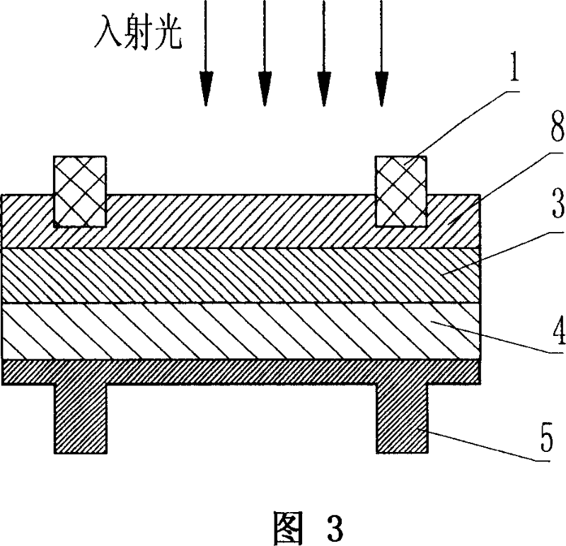
[0017] Fig. 3 is an embodiment of the present invention taking the P-type substrate material as an example, a schematic structural view of an amorphous silicon-crystalline silicon heterojunction solar cell, including: a light-receiving surface electrode 1, an N-type silicon diffusion layer 3, a P-type silicon Substrate layer 4 and back electrode 5. The present invention also prepares a layer of amorphous silicon film layer 8 between the light receiving surface electrode 1 and the N-type silicon diffusion layer 3 on the light-receiving surface side of the solar cell, and the amorphous silicon film layer 8 and the N-type silicon diffusion layer 3 form a different High-quality high-low junction structure, that is, amorphous silicon has the same conductivity type as the crystalline silicon it contacts. Therefore, the lamination sequence between different materia...


PUM


Abstract

The invention discloses a structure of amorphous silicon- crystal silicon heterogeneity node solar cell, a layer of amorphous silicon film is at the photic surface of the solar cell which is between electrode and N type silicon pervasion layer; the amorphous silicon film layer and the N type silicon pervasion layer form a heterogeneity height node structure. The invention adopts the different light absorption property of different semiconductor material and two dimension electron gas effect introduced by semiconductor heterogeneity node to realize the higher photoelectricity transition efficiency than normal crystal silicon solar cell; batter stability for long time and higher photoelectricity transition efficiency than normal amorphous silicon solar cell; and lower series-wound resistance and higher photoelectricity transition efficiency than pure amorphous silicon-monocrystalline silicon heterogeneity node solar cell.

Description

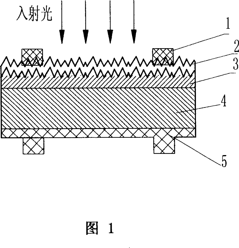
technical field [0001] The invention relates to photovoltaic power generation technology, especially a solar cell made of a combination of crystalline silicon and amorphous silicon. Background technique [0002] A known typical crystalline silicon solar cell has a structure as shown in Figure 1, including a light-receiving surface electrode 1, a passivation / anti-reflection film 2, an N-type silicon diffusion layer 3, a P-type silicon substrate layer 4 and a back surface Electrode 5. [0003] It is known that the photoelectric conversion efficiency of a typical crystalline silicon solar cell is about 15%. Since the P region and N region of a crystalline silicon solar cell use the same crystalline silicon material and have the same energy band structure, the typical value of its forbidden band width is 1.12ev. Roughly speaking, in the quantum process of photoelectric conversion, light quanta with energy equal to the forbidden band width of silicon can excite hole-electron pa...

Claims


Application Information

Patent Timeline
Patent Type & Authority Applications(China)
IPC IPC(8): H01L31/042H01L31/072H01L31/0376H01L31/0747
CPCY02E10/50
Inventor 袁晓李涛勇
Owner SHANGHAI SOLAR ENERGY S&T
Learn More