Method and apparatus for preparing material coating by laser inductive composite melt-coating

A laser induction and cladding technology, applied in metal material coating process, laser welding equipment, coatings, etc., can solve the problems of easy cracking in the cladding layer, heavy cladding preparation work, and low laser cladding efficiency. , to achieve the effect of improving the utilization rate of laser energy, avoiding damage to important components, and avoiding low cladding efficiency

Active Publication Date: 2007-11-14
WUHAN HIVALUE INTELASER LTD
View PDF0 Cites 70 Cited by
  • Summary
  • Abstract
  • Description
  • Claims
  • Application Information

AI Technical Summary

Problems solved by technology

[0003] However, so far, the application of laser cladding technology in industry has not reached the early expected goal. The main reasons include: (1) the one-time investment of high-power laser processing equipment is relatively large, and the maintenance cost is expensive; (2) ) The efficiency of laser cladding is much lower than that of traditional processes, such as surfacing and thermal spraying, so the manufacturing cost per unit area of ​​the coating is relatively high; (3) although laser and thermal spraying can be combined to achieve laser thermal spraying composite cladding technology ( J.Suutala, J.Tuominen, P.Vuoristo.Laser-assisted spraying and laser treatment of thermally sprayedcoatings, Surface & coatings Technology, 201(2006): 1981-1987), which improves the efficiency of laser cladding, but due to laser cladding Due to the characteristics of rapid heating, rapid cooling and solidification, and large thermal stress during the process, when laser...

Method used


Image

  • Method and apparatus for preparing material coating by laser inductive composite melt-coating
  • Method and apparatus for preparing material coating by laser inductive composite melt-coating
  • Method and apparatus for preparing material coating by laser inductive composite melt-coating

Examples


example 1

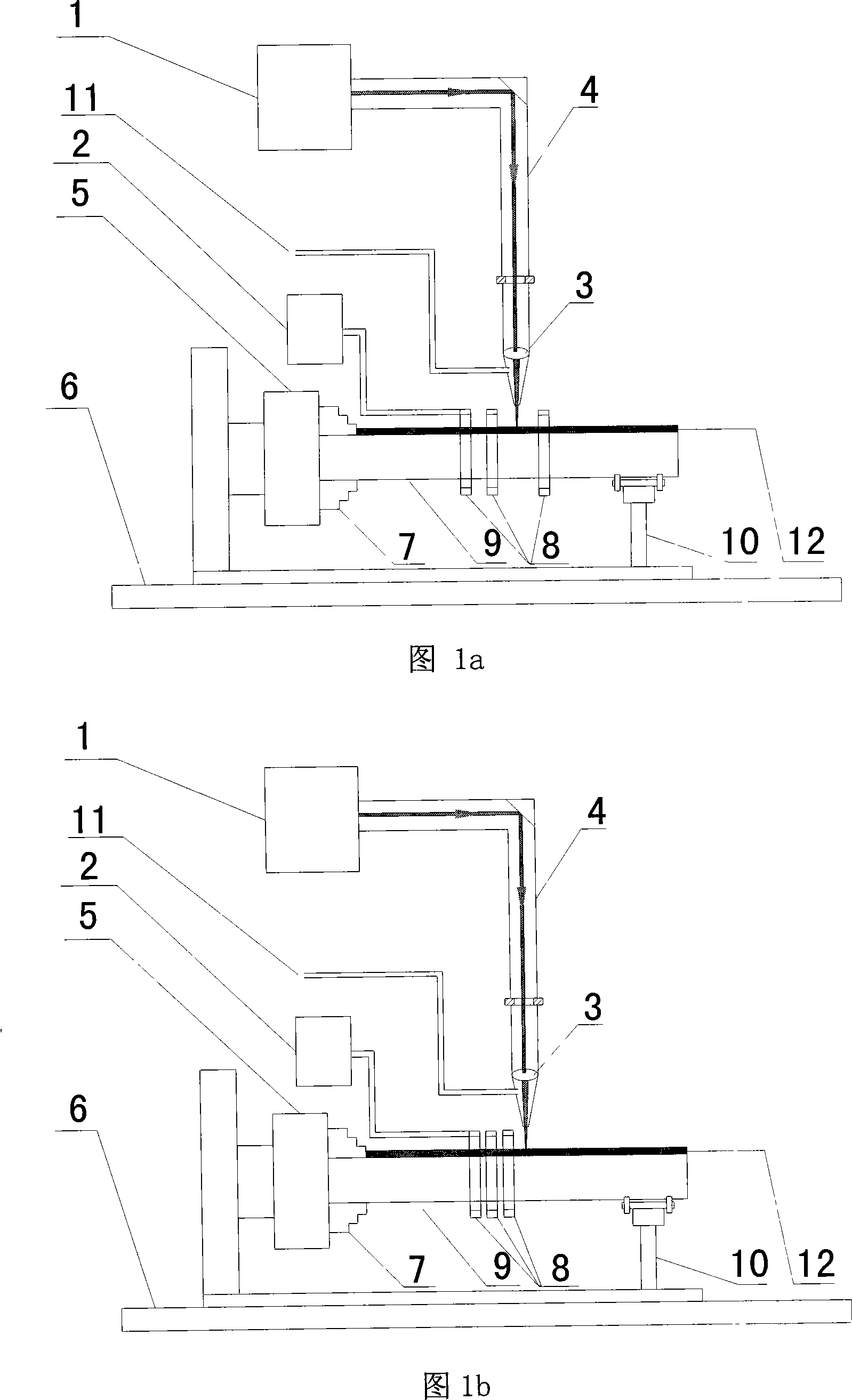
[0050] Select continuous CO 2 Laser, using the device shown in Figure 1a to perform laser induction composite cladding on the outer surface of a tubular metal part with an outer diameter of 110 mm and a wall thickness of 10 mm.

[0051] (1) Sand blasting is carried out to the outer surface of the tubular metal parts;

[0052] (2) Use thermal spraying or cold spraying technology to spray a coating with a thickness of 0.1 mm on the outer surface. The coating material can choose wear-resistant, corrosion-resistant or high-temperature-resistant iron-based, nickel-based or cobalt-based alloy powders, or cermet composite powders composed of the above alloy powders and ceramic particles such as tungsten carbide, titanium carbide, and silicon carbide.

[0053] (3) The distance between the coating on the outer surface of the tubular metal part and the induction heating coil is adjusted to 1 mm, the number of turns of the induction heating coil is 3 turns, and an electric current is pa...

example 2

[0057] Choose a diode laser, and use the device shown in Figure 1b to perform laser induction composite cladding on the outer surface of a tubular metal part with an outer diameter of 300 mm and a wall thickness of 15 mm.

[0058] (1) Sand blasting is carried out to the outer surface of the tubular metal parts;

[0059] (2) Use thermal spraying, cold spraying technology or supersonic flame spraying technology to spray a coating with a thickness of 3.0 mm on the outer surface. The coating material can choose wear-resistant, corrosion-resistant or high-temperature-resistant iron-based, nickel-based or cobalt-based alloy powders, or cermet composite powders composed of the above alloy powders and ceramic particles such as tungsten carbide, titanium carbide, and silicon carbide.

[0060] (3) The distance between the coating on the outer surface of the tubular metal part and the induction heating coil is adjusted to 10 mm, the number of turns of the induction heating coil is 3 turn...

example 3

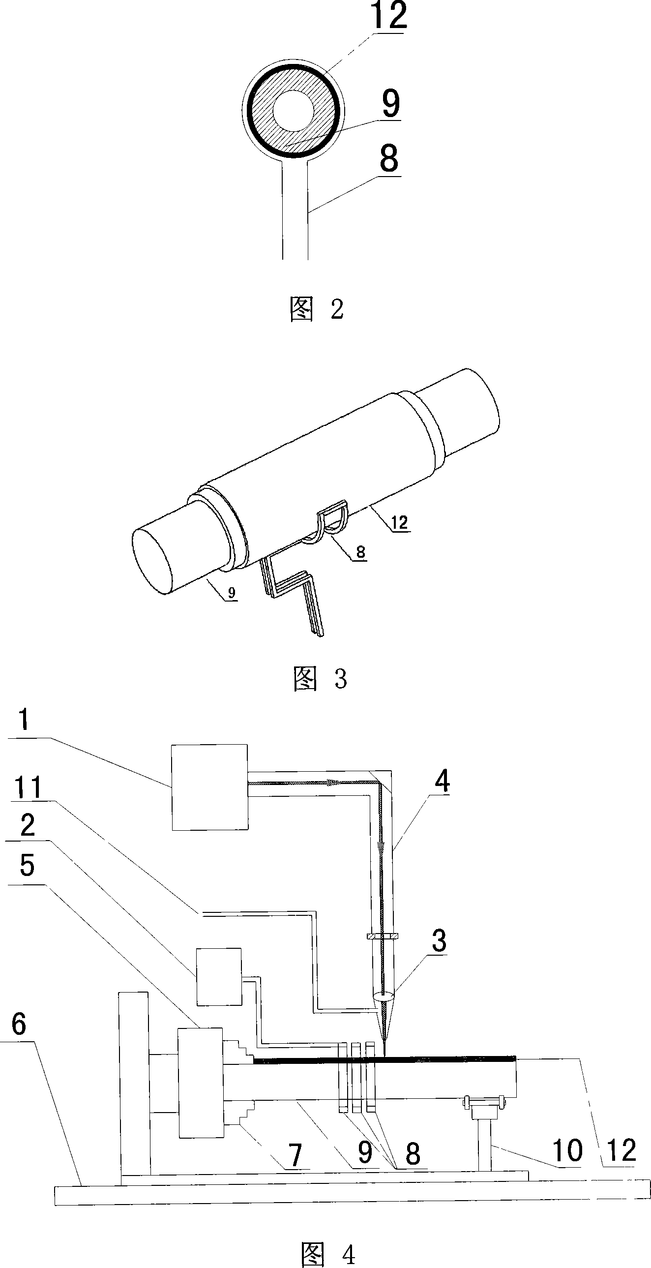
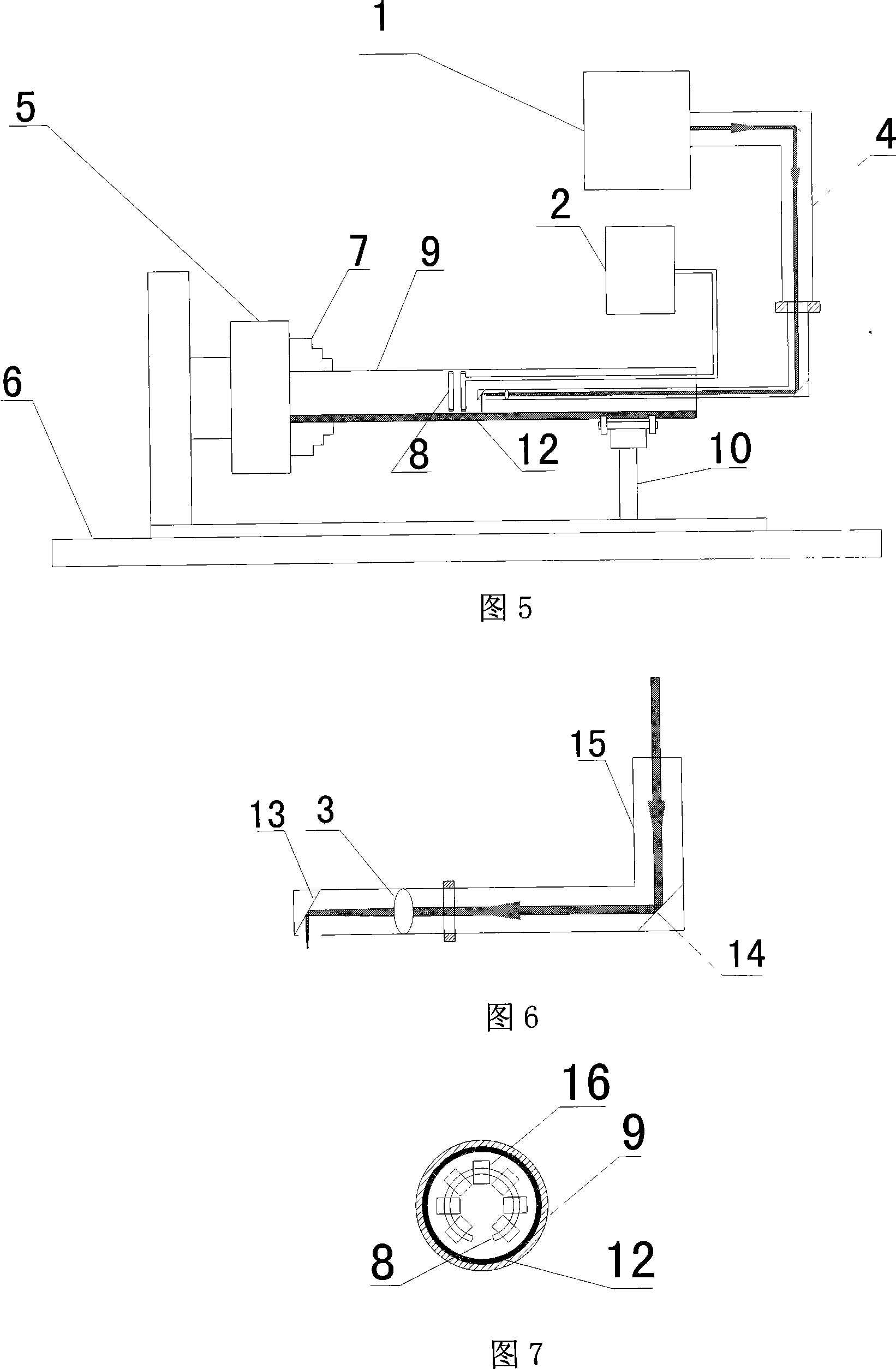
[0064] Select continuous CO 2 Laser, use the device shown in Figure 4 to perform laser induction composite cladding on the surface of the roll with a diameter of D = 600 mm, and this device is also suitable for solid parts such as crankshafts and oil drill pipes.

[0065](1) Sandblasting the surface of the roll first;

[0066] (2) Use thermal spraying, cold spraying technology or supersonic flame spraying technology to spray a coating with a thickness of 1 mm on the surface of the roll. The coating material can choose wear-resistant, corrosion-resistant or high-temperature-resistant iron-based, nickel-based or cobalt-based alloy powders, or cermet composite powders composed of the above alloy powders and ceramic particles such as tungsten carbide, titanium carbide, and silicon carbide.

[0067] (3) The distance between the coating on the surface of the metal parts of the roll and the induction heating coil is adjusted to 5 millimeters, the number of turns of the induction hea...


PUM

PropertyMeasurementUnit
Outer diameteraaaaaaaaaa
Wall thicknessaaaaaaaaaa
Thicknessaaaaaaaaaa

Abstract

The invention discloses a method and its device for laser to induce the compound melt high performance material coating. The invention heats up and coupling the laser beam and the high frequency electromagnetic induction, and realizes the process of laser compound melt with induction heating. The device includes the laser, the laser conducting device, the laser gathering device, the high frequency induction heater, numerically controlled machine tool, and the workpiece holding device. When the device works, the distance of coating of preparing to deal with workpiece surface and induction heating coil is between 1 and 10 millimeter. The versatility of the invention is strong, so it can do the surface treatment with laser to induce the compound melt high performance material coating in the surface of solid assembly of each material and inner and outer surface of tubular part. The characteristic of melt method lies in utilizing the efficiency high merit of hot spray, cold spray, or supersonic flame spray. And induction heating is done at the time of laser melt. The maximum melt linear speed amounts to 0.5-10 meters per minute, which enhances between one time and ten times to the conventional laser melt. The deposition rate of powder is improved between one time and fifteen times than existing laser melt deposition rate, moreover the melt deposit doesn't have the blowhole and the crack.

Description

technical field [0001] The invention belongs to the technical field of laser processing, and in particular relates to a method and a device for preparing a material coating by laser induction composite cladding. Background technique [0002] Laser cladding technology is a process of cladding a layer of material with special properties on the surface of a workpiece by using a high-energy-density laser beam to improve its surface properties. Compared with traditional surfacing and thermal spraying processes, laser cladding technology has the following advantages: (1) The laser beam spot is small and the energy density is high, which can minimize the heat-affected zone and thermal deformation of the workpiece during the cladding process (2) By adjusting the process parameters, the cladding layer with a dilution rate of less than 10% can be obtained; (3) The cladding layer and the substrate are metallurgically bonded, with high bonding strength and not easy to peel off; (4) Thro...

Claims


Application Information

Patent Timeline
IPC IPC(8): C23C24/10B23K26/34
Inventor 曾晓雁胡乾午周圣丰黄永俊
Owner WUHAN HIVALUE INTELASER LTD
Why Eureka
Try Eureka