Biogas cleaning equipment and purifying technique thereof

A technology of purification equipment and purification process, which is applied in combustible gas purification, combustible gas purification/transformation, petroleum industry, etc. It can solve the problems of low methane yield, difficulty in adopting large-scale high-pressure absorption purification process, and low LFG output.

Inactive Publication Date: 2008-01-23
LIAONING KAITIAN RENEWABLE ENERGY & ENVIROMENT
View PDF1 Cites 18 Cited by
  • Summary
  • Abstract
  • Description
  • Claims
  • Application Information

AI Technical Summary

Problems solved by technology

But it has its shortcomings: firstly, it is limited to the separation process, when CH 4 When the concentration is constant, the actual methane yield in its production is only 70%
Domestic PSA method is widely used in chemical industry, equipment and adsorbents do not need to be imported, energy consumption is relatively low, but it also has its disadvantages: limited by process characteristics, when the product concentration is increased, its methane yield will decrease accordingly
In addition, limited by the current domestic landfill conditions, especially the low output of LFG, it is difficult to adopt a large-scale high-pressure absorption and purification process

Method used


Image

  • Biogas cleaning equipment and purifying technique thereof
  • Biogas cleaning equipment and purifying technique thereof

Examples


Embodiment 1

[0072] 1. Processing raw gas volume: 15000m 3 / d LFG

[0073] 2. Composition of raw gas and purified gas (V%)

[0074] CH 4 CO 2 o 2 other

[0075] Raw material gas 55~60 35~40 0.3~0.7 1.8~3.2

[0076] Purified gas 96~98 2~3 0.5~1.0 2~3

[0077] The methane recovery rate is >96%, and the purified gas contains H 2 S3

[0078] 3. Process conditions

[0079] 1) Gas-liquid ratio: m 3 Gas / m 3 Solution 25~35

[0080] m 3 Gas / m 3 stock solution * 50~70

[0081] 2) Solution concentration 2.56~4.28kmol / m 3 ;Concentration of poor solution 1~2.5LCO 2 / L solution

[0082] 3) Temperature: (℃)

[0083] Absorption tower: 45-55 at the top of the tower

[0084] Tower bottom 55~65

[0085] Desorption tower: bottom 102~108

[0086] Tower top 85~92

[0087] 4) Tower pressure

[0088] Absorption tower: 35~40kPa

[0089] Desorption tower: normal pressure

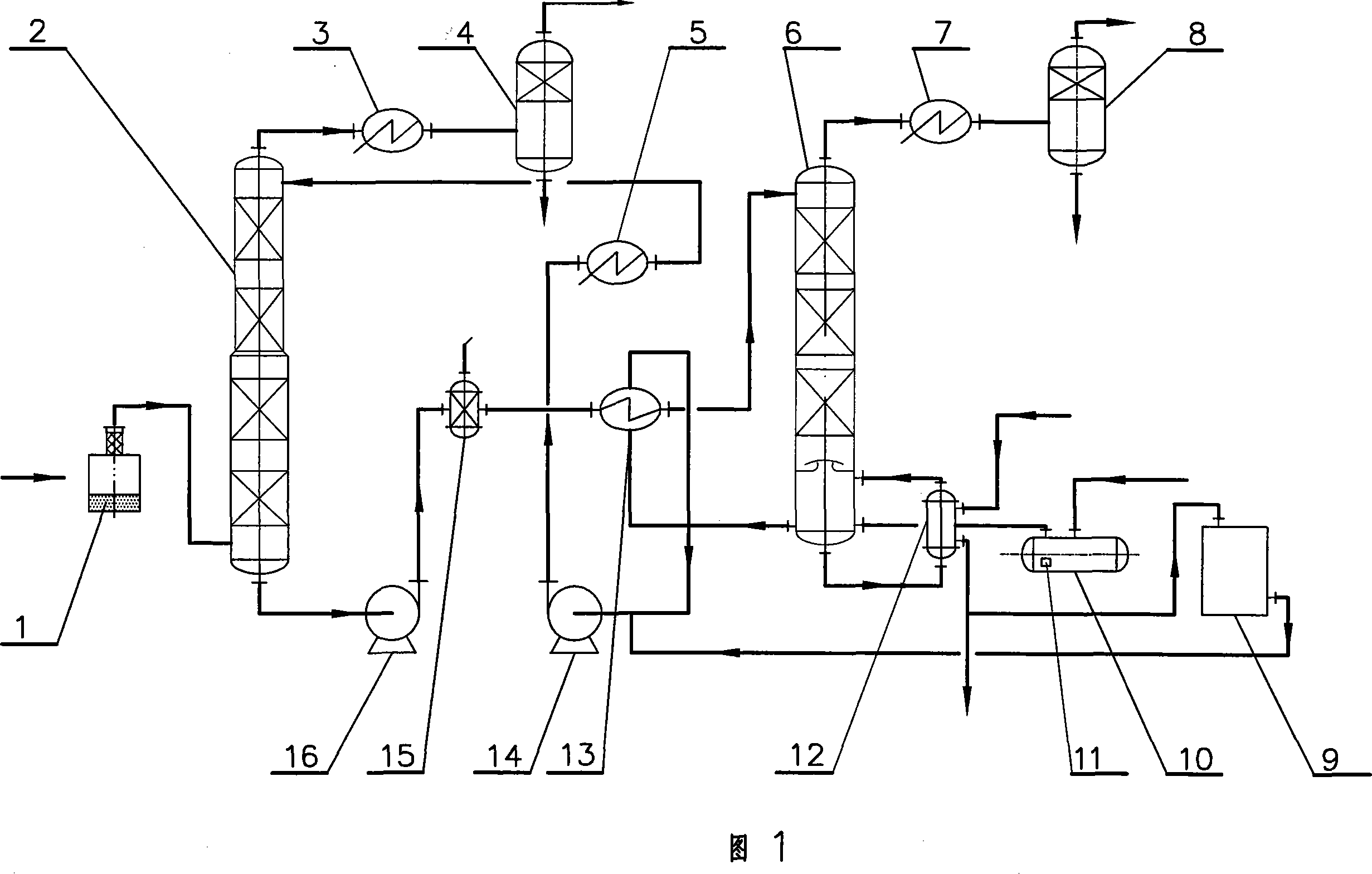
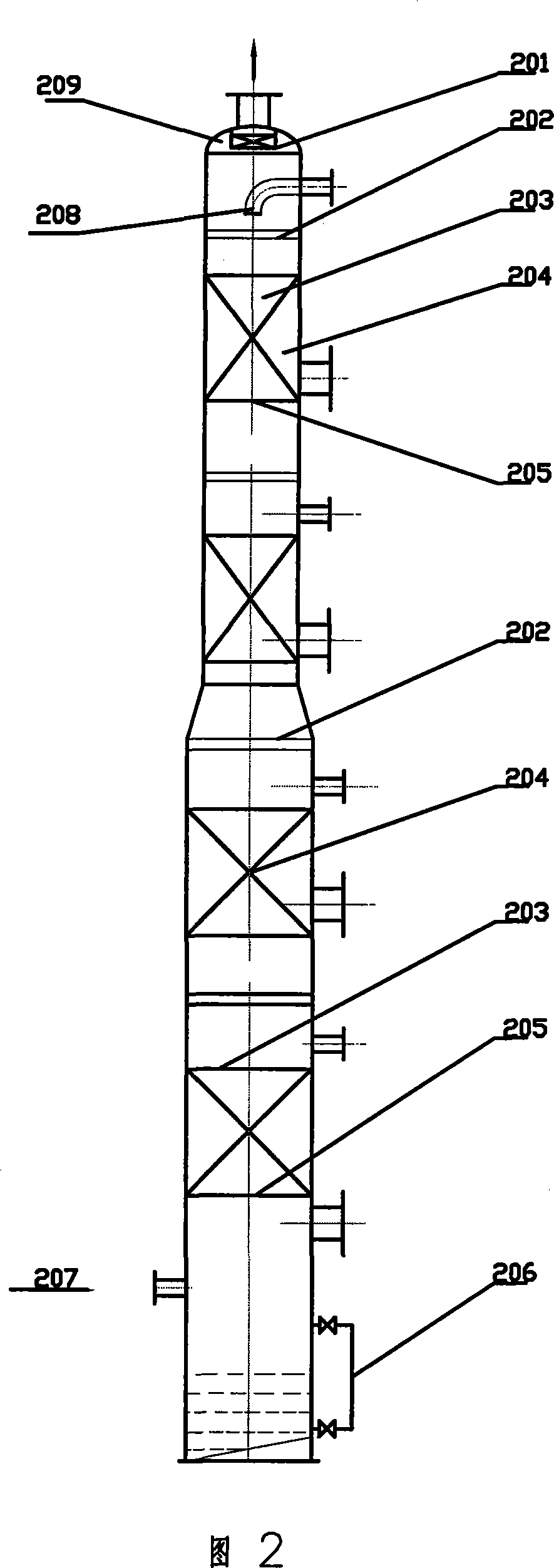
[0090] 4. Main equipment

[0091] Absorption tower:...

Embodiment 2

[0094] 1. Processing raw gas: fermented biogas (biogas)

[0095] Scale: 40000m 3 / d

[0096] 2. Composition of raw gas and purified gas: (V%)

[0097] CH 4 CO 2 o 2

[0098] Raw material gas 55~65 30~40 0.2~0.6

[0099] Purified gas 96~98 <0.8 0.5~1.0

[0100] CH 4 Recovery rate > 96%, H in purified gas 2 S depends on raw material gas H 2 S content and take technological measures, generally can be 3 .

[0101] 3. Process conditions

[0102] 3) Gas-liquid ratio: 80-90m 3 Gas / m 3 the solution

[0103] 4) Solution concentration: 2.56~4.28kmol / m 3

[0104] Barren solution concentration: 1.5~2.5 LCO 2 / L solution

[0105] 5) Temperature (℃)

[0106] Absorption tower: 55-60 at the top of the tower

[0107] Tower bottom 60~70

[0108] Desorption tower: 105~110 at the bottom of the tower

[0109] Tower top 88~92

[0110] 6) Tower pressure

[0111] Absorption tower: 0.5MPa

[0112] Desorption tower: 15~20kPa.

[0113] 4....


PUM

PropertyMeasurementUnit
heightaaaaaaaaaa
diameteraaaaaaaaaa
clearance rateaaaaaaaaaa

Abstract

The invention relates to the biogenetic gas purification field, in particular to a biogenetic gas purifying equipment and a purifying technique. The equipment comprises an absorption tower, a desorption tower, a reboiler, a heat exchanger, a cooler, a separator, an absorbent holding tank and a pump. The invention is characterized in that: firstly, the absorption tower is a different diameter tower featuring with small upper section and large lower section and the upper-and-lower tower diameter ratio ranges between 0.75 and 0.85; secondly, a catcher with metal mesh is added inside the former material gas inlet of the adsorbption tower; thirdly, a fiber rod filter is arranged at the outlet of the rich solution outlet of the absoption tower. The technique adopts the water solution as the absorption solution with MEDA main solute and multi-amine activator, and the operation parameters are 30 kPa to 40 kPa operation pressure inside the tower ranges, 45 DEG C. to 55 DEG C. temperature at the tower top of the tower and 50 DEG C. to 60 DEG C. at the bottom, 25 to 35 (m3G / m3L) gas-liquid ratio, 2.56 to 4.28Kmol per m3 absorption solution concentration, and 1 to 2.5LCO2 per L lean solution concentration. The invention is used to remove the impurities of CO2, H2S, HCN and the organic sulfur from the biogenetic gas, coal bed gas and coke-oven gas to meet the purification requirement.

Description

technical field [0001] The invention relates to the field of biogas purification, in particular to biogas purification equipment and a purification process thereof. It can be used for biogas and other industrial gases, such as coal bed methane, coke oven gas, etc. to remove CO 2 、H 2 S, HCN, organic sulfur and other impurities meet the requirements of purification. Background technique [0002] Biogas refers to the combustible gas produced by microbial degradation and methanation of organic matter in living organisms under anaerobic conditions. Artificially produced biogas mainly includes landfill gas (LFG) produced after domestic waste is landfilled, biogas produced by fermentation of plants such as garbage, sewage, sludge, manure, straw, etc. Its main component is CH 4 , CO 2 , a small amount of H 2 、C m h n and a small amount of H 2 S, organic sulfur and other impurities. At present, the purification and utilization of domestic biogas, especially landfill gas (L...

Claims


Application Information

Patent Timeline
Patent Type & Authority Applications(China)
IPC IPC(8): C10L3/00C10K1/00
CPCY02E50/346Y02E50/30
Inventor 计中坚刘士军
Owner LIAONING KAITIAN RENEWABLE ENERGY & ENVIROMENT
Why Eureka
Try Eureka