
Novel aluminum emitter junction N type single crystal silicon solar battery

A solar cell, emitter junction technology, used in photovoltaic power generation, circuits, electrical components, etc.

Active Publication Date: 2008-03-26
NINGBO ULICA SOLAR SCIENCE & TECHNOLOGY CO LTD
View PDF0 Cites 30 Cited by
  • Summary
  • Abstract
  • Description
  • Claims
  • Application Information

AI Technical Summary

Problems solved by technology

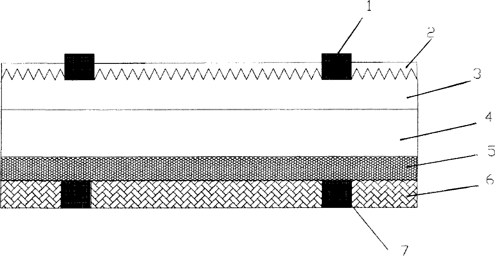
[0003] In order to solve the problems of the foregoing process, the present invention provides a novel aluminum back emitter junction N-type monocrystalline silicon solar cell; through two times of screen printing aluminum paste and two times of sintering, the sintering of the aluminum-silicon alloy and the sintering of the back electrode Carry out separately, successfully solved this difficult problem; The solar cell structure of the present invention is, from upper layer to lower layer, is successively:

Method used


Image

  • Novel aluminum emitter junction N type single crystal silicon solar battery

Examples


Embodiment Construction

[0033] (1) The N-type monocrystalline silicon wafer with a resistivity of 0.2-15Ω.cm is subjected to chemical pre-cleaning and textured etching;

[0034] N-type monocrystalline silicon wafers with a resistivity of 0.2-15Ω.cm are placed in 0.5%-2% Na 2 SiO 3 Ultrasonic pre-cleaning in the solution for 5-10 minutes, rinse with deionized water, remove the surface damage layer with heated 20% NaOH or KOH solution, and then add a small amount of alcohol or isopropanol with 1%-2% NaOH or KOH solution The suede surface is corroded, soaked in dilute hydrochloric acid and dilute hydrofluoric acid, rinsed with deionized water, and dried.

[0035] (2) On the front side of the N-type single crystal silicon wafer, phosphorus is diffused N + Layer: N + Layer adopts conventional gas phase carrying POCl 3 Thermal diffusion, silicon wafers are placed back to back in a quartz boat during diffusion, the temperature is 850-920°C, and the sheet resistance is controlled at 20-60Ω / cm 2 .

[00...


PUM

PropertyMeasurementUnit
Thicknessaaaaaaaaaa
Resistivityaaaaaaaaaa

Abstract

This invention provides a new type of type-N monocrystal silicon solar cells of Al back emission junction including: 1, Ag grating positive electrode, 2, SiNx reduction reflection layer of 80nm thick, 3, a positive N+phosphor diffusion layer of 0.3-0.5um thick, 4, type-N monocrystal silicon chip with the resistivity of 0.2-15ohmcm, 5, a P+ Al-Si alloy layer, 6,a back Al electrode, 7, a back AgAl master grating elctrode, in which, sintering of AlSi alloy and that of the back electrode are separated by two times of silk screen printing Al slurry and two times of sintering.

Description

technical field [0001] The invention relates to a novel aluminum back emitter junction N-type single crystal silicon solar cell structure and production process. Background technique [0002] The mature technology of N-type silicon solar cells mainly uses boron diffusion to prepare the back P-type emitter junction. In order to further simplify the process and reduce the cost, a new process is generally adopted. The screen printing aluminum paste is sintered at one time, and the aluminum back emitter junction and aluminum back electrode are completed at one time. However, we have encountered a problem that is difficult to solve, that is, if the back is completely covered with aluminum, the problems of electrode solderability and firmness cannot be solved; if the busbar position is vacant when the aluminum paste is printed on the back to print silver-aluminum paste, it will lead to the position of the busbar on the back. The aluminum emitter junction is missing, and the silve...

Claims


Application Information

Patent Timeline
IPC IPC(8): H01L31/042H01L31/072H01L31/036H01L31/0224H01L31/18H01L31/074
CPCY02E10/52Y02E10/50Y02P70/50
Inventor 胡宏勋李华维徐晓群孙劢斌陈斌黄跃文唐则祁
Owner NINGBO ULICA SOLAR SCIENCE & TECHNOLOGY CO LTD
Learn More