Method for manufacturing small spiral bevel gear
A technology of spiral bevel gear and manufacturing method, which is applied in the field of small spiral bevel gear manufacturing to achieve the effects of high production efficiency, short production cycle and high precision
- Summary
- Abstract
- Description
- Claims
- Application Information
AI Technical Summary
Problems solved by technology
Method used
Image

Examples
Embodiment 1
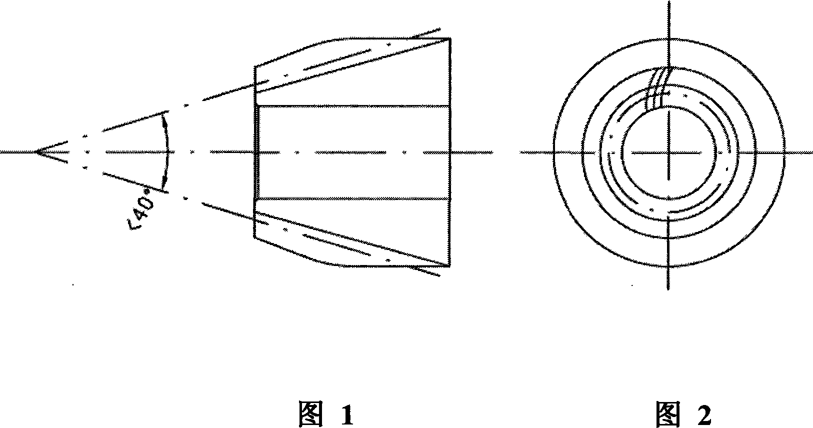
[0027] Small spiral bevel gear after the forming of the present invention is as shown in Figure 1 and Figure 2, and its manufacturing method is as follows:
[0028] 1. First mix 94kg of 100 mesh atomized iron powder, 1kg of 200 mesh nickel powder, 1kg of 150 mesh copper powder, 0.6kg of 150 mesh carbon powder, and 0.8kg of 150 mesh zinc stearate.
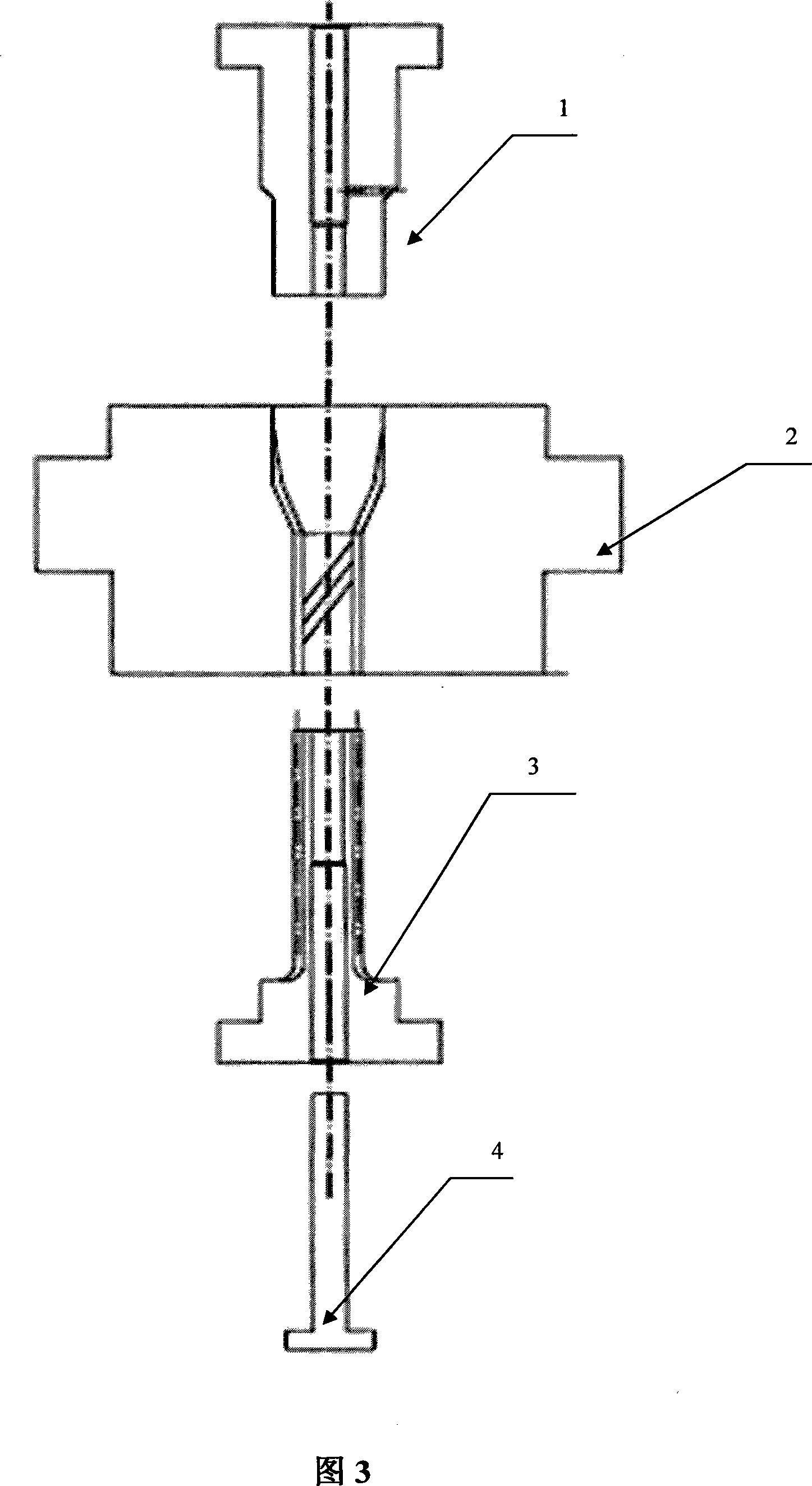
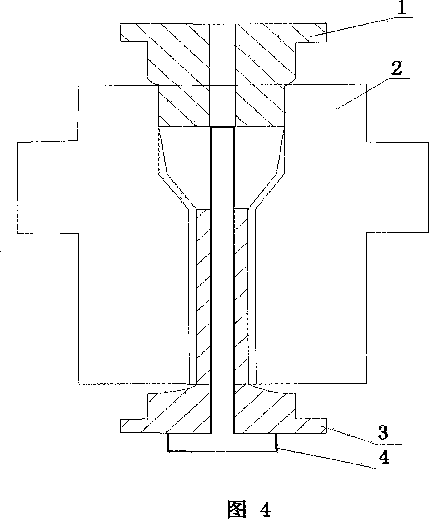
[0029] 2. Put the mixed powder into the hopper, and transport it through the powder delivery pipe to the mold cavity composed of the upper die punch 1, the copying female die 2, the lower die punch 3, and the core rod 4;
[0030] 3. Pressing is performed under a pressure of 500-650Mpa. During pressing, the upper die punch 1 remains stationary, the female die 2 is forced to float, and the lower die punch 3 performs a spiral movement along the imitation spiral line of the female die 2 with the axis as the center. The female mold 2 is forcibly pulled down at the end of the pressing, and the lower die punch 3 performs a spiral motion al...
Embodiment 2
[0033] The consumption relation of the used raw material of small spiral bevel gear among the present invention is as follows, other is the same as embodiment 1.
[0034] Among them, 150 order atomized iron powder 98kg, 150 order nickel powder 3kg, 150 order copper powder 1kg, 200 order carbon powder 0.6kg, 200 order zinc stearate 0.3kg among the raw materials.
Embodiment 3
[0036] The amount of raw materials used in the small spiral bevel gear manufactured by the present invention is as follows, and the others are the same as in Embodiment 1.
[0037] In the raw material, 200 mesh atomized iron powder 96kg, 200 mesh nickel powder 3kg, 150 mesh copper powder 1kg, 150 mesh carbon powder 0.3kg, 150 mesh zinc stearate 0.5kg.
PUM
| Property | Measurement | Unit |
|---|---|---|
| Density | aaaaa | aaaaa |
Abstract
Description
Claims
Application Information