Eureka AIR delivers breakthrough ideas for toughest innovation challenges, trusted by R&D personnel around the world.

Method of using ammonia process to remove carbon dioxide from generating plant smoke gas and system thereof

A carbon dioxide and flue gas technology, applied in chemical instruments and methods, separation methods, air quality improvement, etc., can solve problems such as difficult to effectively remove carbon dioxide, overcome inherent defects, reduce investment and operating costs, and increase contact area effect

Inactive Publication Date: 2008-07-30
WUHAN KAIDI ELECTRIC POWER ENVIRONMENTAL
View PDF0 Cites 26 Cited by
  • Summary
  • Abstract
  • Description
  • Claims
  • Application Information

AI Technical Summary

Problems solved by technology

Due to the inherent shortcomings of the above ammonia bubbling and filler absorption methods and the particularity of the flue gas at the tail of the power plant boiler, it is difficult to achieve the purpose of effectively removing carbon dioxide from the flue gas

Method used


Image

  • Method of using ammonia process to remove carbon dioxide from generating plant smoke gas and system thereof

Examples


Embodiment Construction

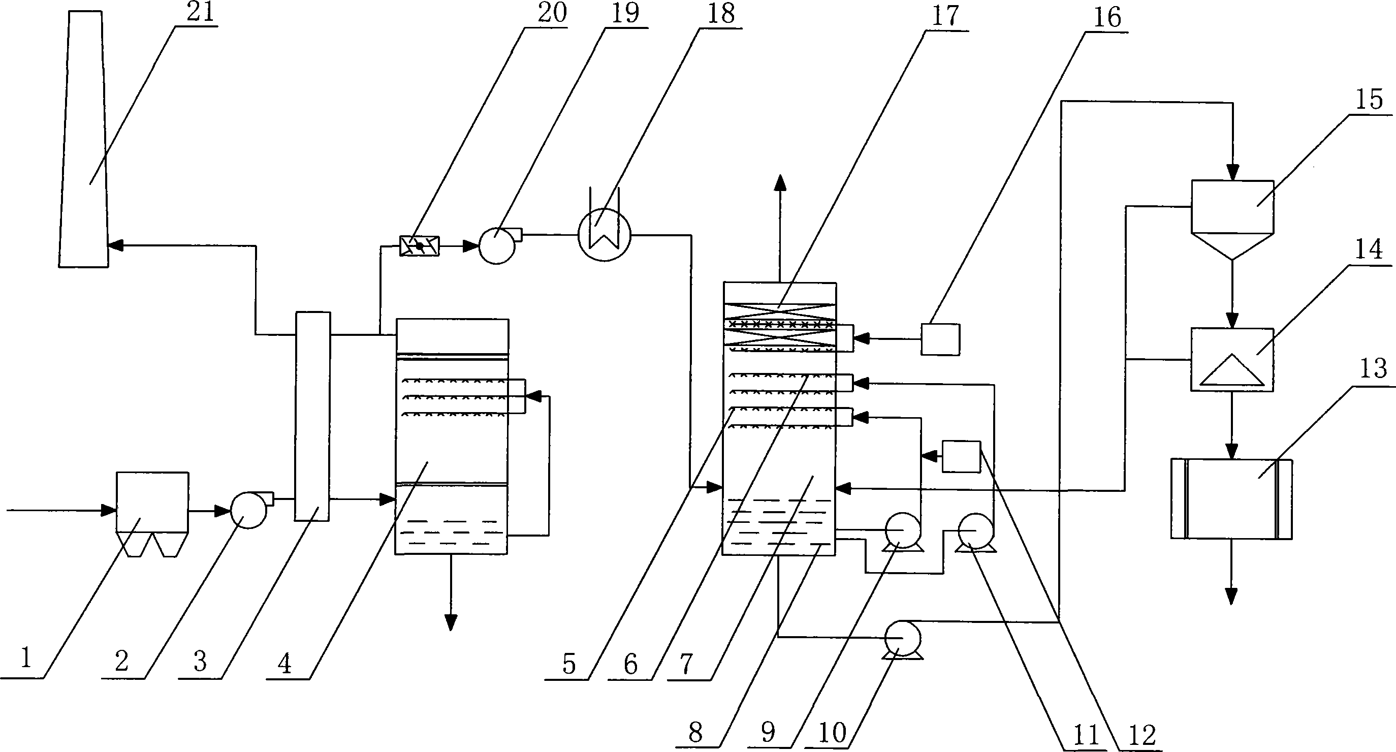
[0026] Below for the flue gas discharged by a power station boiler unit, the present invention will be further described in detail in conjunction with the accompanying drawings:

[0027] The traditional flue gas desulfurization system shown in the figure uses limestone absorbent for desulfurization, which includes an electric precipitator 1, and the smoke outlet of the electric precipitator 1 passes through the inlet of the booster fan 2, the flue gas heat exchanger 3 and the desulfurization reaction tower 4 in sequence. The smoke outlets are connected, and the smoke outlet of the desulfurization reaction tower 4 is divided into two paths, one path is directly connected to the chimney 21 through the flue gas heat exchanger 3, and the other path is sequentially passed through the flue gas bypass baffle plate 20, the pressurizing fan 19, and the cooler 18 is connected with the lower flue gas inlet of carbon dioxide absorption tower 7.

[0028] The system for removing carbon diox...


PUM


Abstract

The invention relates to a method for removing carbon dioxide from flue gas of power station by employing ammonia process and a system thereof. The method of the invention is that the spray of an ammonia empty tower circulation removes carbon dioxide; the ammonium hydrogen carbonate fell to tower bottom is divided into three paths: the first path is to circulate by means of a primary spray device at the upper part of a deposition pond; the second path is to circulate by means of a secondary spray device at the middle part of the deposition pond; the third path is that pumping the ammonium hydrogen carbonate out from the bottom of the deposition pond to process fertilizer ammonium bicarbonate after rotational flow, centrifugation and drying treatment; the flue gas after being removed carbon dioxide and defogged is emitted into atmosphere. The system comprises the primary spay device, the secondary spray device, a carbon dioxide absorbing tower of the defogging device from top to bottom, wherein, the primary spray device and the secondary spray device are respectively connected with the upper part and the middle of the deposition pond via a primary slurry circulation pump and a secondary circulation pump, and the water inlet of the primary spray device is provided with a ammonia supply device; the bottom of the deposition pond is serially connected with a cyclone separator, a centrifuge and a drier via a fluid thickening circulation pump; the invention is especially suitable for treating flue gas of power station with large flux and low carbon dioxide concentration, in addition, ammonium bicarbonate fertilizer can be obtained.

Description

technical field [0001] The invention relates to a purification treatment technology for flue gas at the tail of a coal-fired power plant boiler, in particular to a method and system for removing carbon dioxide from power plant flue gas by ammonia method. Background technique [0002] Atmospheric greenhouse effect is one of the most important environmental problems faced by human beings. Carbon dioxide is the main greenhouse gas, thermal power plants are the concentrated emission source of carbon dioxide, and its carbon dioxide emission accounts for about 30% of the total carbon dioxide emission caused by human activities. A 600MW thermal power plant can emit up to 500 tons of carbon dioxide per hour. Therefore, in order to reduce the carbon dioxide content in the atmosphere, the most important thing is to reduce the amount of carbon dioxide discharged into the atmosphere by the exhaust gas of the power plant boiler. [0003] At present, the methods for carbon dioxide treat...

Claims


Application Information

Patent Timeline
IPC IPC(8): B01D53/62
CPCY02A50/20Y02C20/40
Inventor 朱敬韩旭高翔鹏余福胜李瑞鑫
Owner WUHAN KAIDI ELECTRIC POWER ENVIRONMENTAL
Why Eureka
Eureka Blog
Learn More