Cathode for lithium ion secondary battery and lithium ion secondary battery

A secondary battery, lithium ion technology, used in secondary batteries, secondary battery parts, battery electrodes, etc., can solve the problems of not yet reached the negative electrode active material layer, negative electrode active material constraints, no records, etc., to achieve charge and discharge. The effect of excellent cycle characteristics, high output power, high battery capacity and energy density

Inactive Publication Date: 2008-07-30
PANASONIC CORP
View PDF1 Cites 5 Cited by
  • Summary
  • Abstract
  • Description
  • Claims
  • Application Information

AI Technical Summary

Problems solved by technology

In addition, even if the end of the columnar body does not peel off, the stress generated during the expansion and contraction of the charge and discharge will concentrate on the interface between the central part of the columnar body and the negative electrode current collector, thereby inevitably causing the columnar body to detach from the negative electrode current collector. Partial peeling on the negative electrode current collector, deformation of the negative electrode current collector, etc.
Therefore, the technique of Patent Document 1 has not reached the level of sufficiently and reliably preventing the peeling of the negative electrode active material layer.
In addition, the technology of Patent Document 1 is limited to materials whose negative electrode active materials are cracked due to charge and discharge, so the available negative electrode active materials are limited.
Furthermore, in Patent Document 1, there is no description at all of the technology for preventing the propagation of peeling when the negative electrode active material layer is partially peeled from the negative electrode current collector.

Method used


Image

  • Cathode for lithium ion secondary battery and lithium ion secondary battery
  • Cathode for lithium ion secondary battery and lithium ion secondary battery
  • Cathode for lithium ion secondary battery and lithium ion secondary battery

Examples


Embodiment 1

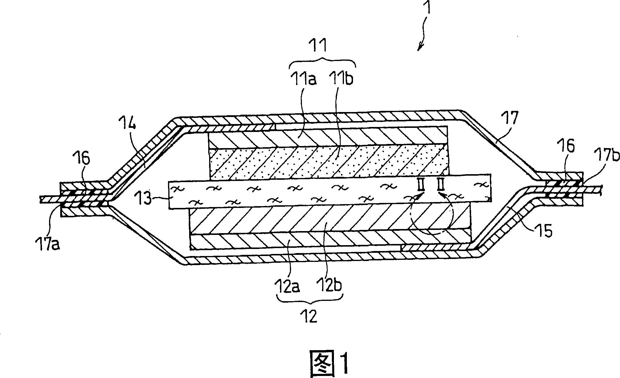
[0080] A lithium ion secondary battery having the same structure as lithium ion secondary battery 1 shown in FIG. 1 was produced by the following method.

[0081] (1) Production of positive electrode

[0082] 10g of lithium cobalt oxide (LiCoO 2 , positive electrode active material) powder, 0.3g acetylene black (conductive agent), 0.8g polyvinylidene fluoride powder (binder) and 5ml N-methyl-2-pyrrolidone (NMP) are fully mixed to prepare the positive electrode Mixture slurry. This positive electrode mixture slurry was coated on one side of an aluminum foil (positive electrode current collector) having a thickness of 20 μm, dried, and then rolled to form a positive electrode active material layer. Thereafter, the positive electrode was cut into a square shape with a side of 30 mm. In the obtained positive electrode, the positive electrode active material layer carried on one side of the aluminum foil had a thickness of 70 μm and a size of 30 mm×30 mm. A positive electrode l...

Embodiment 2

[0116] Except having changed the roll for convex part formation into the following roll for convex part formation, it carried out similarly to Example 1. First, as in Example 1, a ceramic layer made of chromium oxide was formed on the surface of an iron roll. Then, a circular concave portion with a diameter of 12 μm and a depth of 3 μm, that is, a first hole, was formed on the surface of the ceramic layer by laser processing. The 1st hole was designed as the closest packing configuration with a distance between axes of 20 μm. In addition, the bottom of the first hole was processed to have the same shape as that of the bottom of the first hole in Example 1, and the length from the surface of the ceramic layer to the center of the bottom of the first hole was 3 μm. Next, a second hole, which is a circular recess with a diameter of 8 μm and a depth of 3 μm, was formed at the bottom of the first hole so that the axis thereof coincided with that of the first hole. The second hole...

Embodiment 3

[0119] A lithium ion secondary battery of the present invention was produced in the same manner as in Example 1 except that the negative electrode current collector was changed to the following negative electrode current collector.

[0120] On the surface of alloy copper foil (trade name: HCL-02Z, manufactured by Hitachi Electric Cable Co., Ltd.), a dry film photoresist (trade name: PHOTE RY-3300, manufactured by Hitachi Chemical Co., Ltd.) with a thickness of 6 μm was attached . In addition, small circular dots with a diameter of 8 μm were printed on the resin mask. The circular dots were set as the most closely packed configuration with a center-to-center distance of 20 μm. This resin mask was placed on a dry film photoresist, exposed to i-rays using a collimated light aligner, and then developed in an aqueous solution of sodium carbonate at a concentration of 1% by weight to form a photoresist. picture of. Next, copper protrusions are formed in the openings of the photor...


PUM

PropertyMeasurementUnit
diameteraaaaaaaaaa
heightaaaaaaaaaa
thicknessaaaaaaaaaa

Abstract

The present invention provides a negative electrode, which includes: a negative electrode current collector; a first protrusion, which is arranged to extend from the surface of the negative electrode current collector to the outside of the negative electrode current collector, and forms a peeling on at least a part of the surface Propagation preventing part; a negative electrode active material layer, which contains a negative electrode active material, and is provided on at least the top surface of the first convex part. According to this configuration, the peeling of the negative electrode active material layer from the negative electrode current collector and the accompanying reduction in current collection performance can be suppressed, and further deformation of the negative electrode itself can be suppressed. The lithium ion secondary battery containing the negative electrode has high battery capacity and energy density, excellent charge and discharge cycle characteristics, and can continue to perform high output stably for a long time.

Description

technical field [0001] The present invention relates to a negative electrode for a lithium ion secondary battery and a lithium ion secondary battery. More specifically, the present invention mainly relates to improvement of negative electrodes for lithium ion secondary batteries. Background technique [0002] Recently, with the widespread use of portable electronic devices such as personal computers, mobile phones, and mobile devices, the demand for batteries as power sources for portable electronic devices has increased significantly. The batteries used in portable electronic devices are not only required to be used at room temperature, but also require a large battery capacity, high energy density and excellent charge-discharge cycle characteristics. As one of such batteries, lithium ion secondary batteries are known, which include: a positive electrode containing a positive active material capable of intercalating and deintercalating lithium ions reversibly; negative el...

Claims


Application Information

Patent Timeline
Patent Type & Authority Applications(China)
IPC IPC(8): H01M4/02H01M10/40H01M4/13H01M4/64H01M10/0525
CPCH01M4/661H01M4/70H01M4/742H01M10/0525H01M2004/025H01M2004/027Y02E60/10H01M4/02H01M10/02
Inventor 古结康隆岩本和也山本泰右
Owner PANASONIC CORP
Why Eureka
Try Eureka