Leadless high-temperature electronic solder and preparation

A lead-free solder and lead electronics technology, applied in Sn-Sb-Cu-Ni-X multi-component lead-free high-temperature electronic solder and preparation, high-temperature lead-free solder and preparation fields, can solve the problem of wetting in the solid-liquidus interval It can improve the anti-oxidation ability, reduce the dissolution rate and improve the mechanical properties.

Inactive Publication Date: 2008-08-13
ZHEJIANG METALLURGICAL RES INST
View PDF3 Cites 21 Cited by
  • Summary
  • Abstract
  • Description
  • Claims
  • Application Information

AI Technical Summary

Problems solved by technology

At present, there are very few studies on the lead-free use of high-Pb solder. The reports in the literature and patents mainly include 80Au-Sn, Bi-based alloys, Zn-A1-based alloys and Sn-Sb-based alloys, but these alloys have their own characteristics. obvious flaw
[0003] The melting point of 80Au-Sn eutectic solder is 280°C, which is the closest to the melting point of high Pb solder, but the cost of this solder is too high, and it is mainly used for optoelectronic packaging, high reliability (such as InP laser diodes), high-power electronics Device circuit hermetic packaging and chip packaging
[0004] Chinese patent CN155896A proposes to replace the high Pb solder with a Bi-Ag alloy containing 2% to 18wt.% of Ag. The alloy has a suitable melting point and a solidus temperature greater than 262.5°C, but the alloy has high brittleness, poor processability, and A series of problems such as weak matrix bonding strength, wide solid-liquidus range, and poor wettability on Cu and Ni substrates
However, when the Sb content is low (<10%), the melting point of the Sn-Sb binary alloy is relatively low, which is unfavorable for the reliability of solder joints that need to withstand high temperature packaging processes
Moreover, the interface reaction between the alloy and the Cu matrix is ​​very fast, resulting in particularly severe corrosion of Cu.
This will cause two problems: first, the Cu pads or pins in electronic packaging are usually small, and they can be completely melted in a short time (3-5s), resulting in the failure of the solder joints. The dissolution of Cu pads or pins will also lead to changes in the composition of the liquid alloy, and the instability of this composition will also have a greater impact on the reliability of the product
However, this alloy still has the problem of fast corrosion of Cu or Ni substrate pads; moreover, this series of alloys has poor oxidation resistance, and a large amount of tin slag will be produced during high temperature welding.

Method used


Image

  • Leadless high-temperature electronic solder and preparation
  • Leadless high-temperature electronic solder and preparation
  • Leadless high-temperature electronic solder and preparation

Examples


Embodiment 1

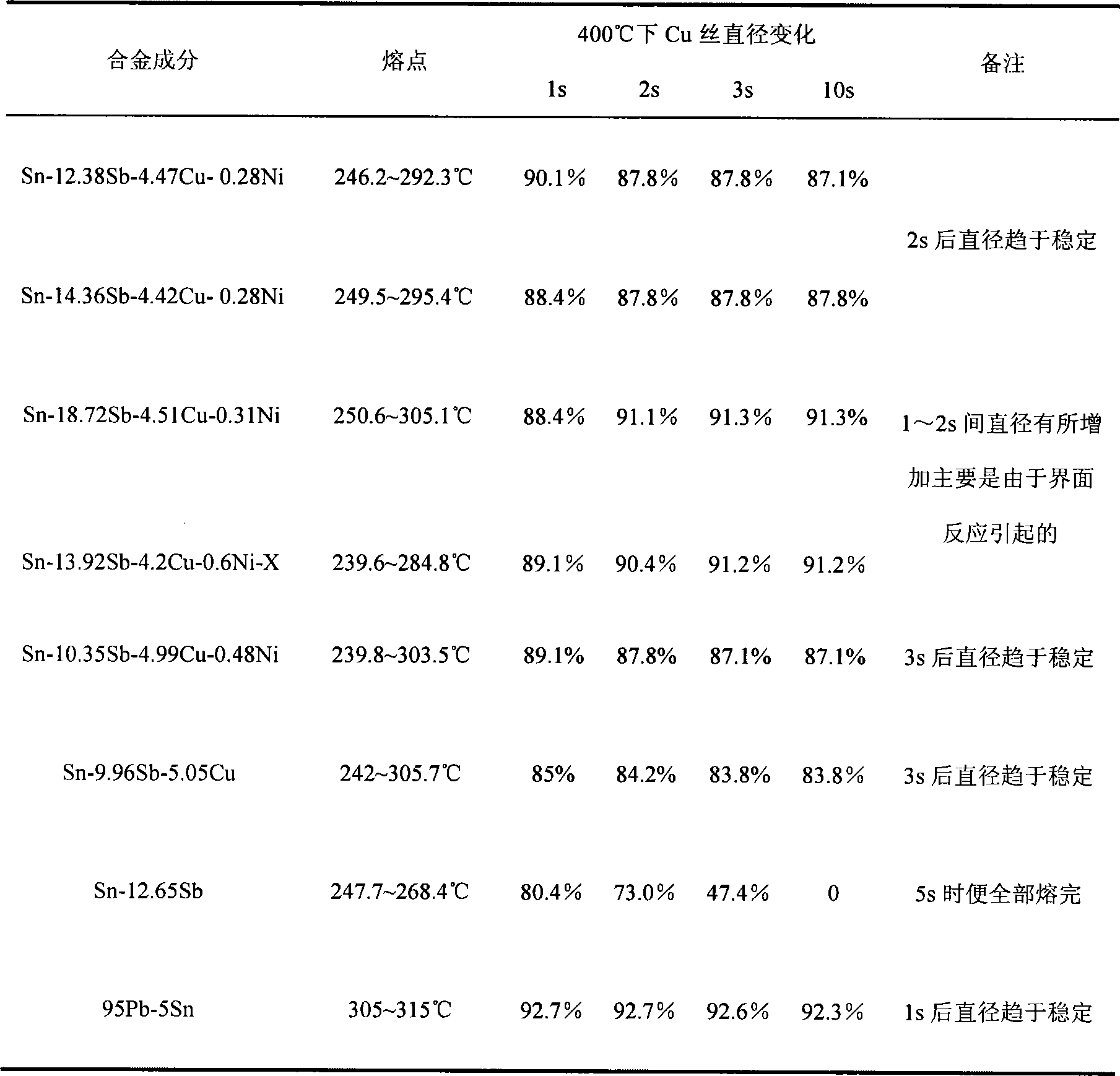
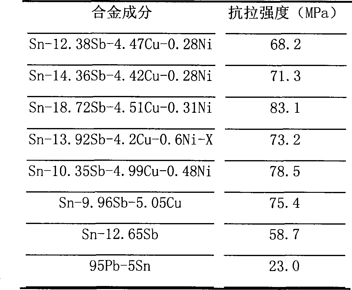
[0026] The alloy composition and its weight percentage are: 12.38% Sb, 4.47% Cu, 0.28% Ni, the rest is Sn and some usual impurity elements. Through DSC measurement, the melting point range of the alloy is 246.2~292.3°C, and the tensile strength is 68.2MPa, see Table 1 and Table 2 respectively.

[0027] The Cu wire with a diameter of 0.15 mm was immersed in the molten solder for reaction, and the corrosion rate of the alloy to the Cu matrix was investigated by measuring the diameter of the Cu wire after dipping for different times. The experimental results show that at a temperature of 400°C, the corrosion behavior of the alloy to Cu mainly occurs within 2s, the corrosion rate of Cu wire is 12.2%, and the diameter of Cu wire is basically stable after 2s, as shown in Table 1.

[0028] The preparation method of the present invention is as follows: it is to heat the prepared various alloy elements at 850-900° C. for 1-2 hours in a vacuum melting furnace or a non-vacuum melting fur...

Embodiment 2

[0032] The alloy composition and its weight percentage are: 14.36% Sb, 4.42% Cu, 0.28% Ni, the rest is Sn and some impurity elements usually. The melting point measured by DSC is: 249.5~295.4°C, and the tensile strength is 71.3MPa.

[0033] The corrosion behavior of the alloy to Cu mainly occurs within 2s, and the corrosion rate of the 0.15mm Cu wire is 12.2%, and the diameter of the Cu wire is basically stable after 2s.

Embodiment 3

[0035] The alloy is refined according to the following composition and weight percentage: Sb18.72%, Cu4.51%, Ni0.31%, and the rest is pure Sn and usual trace impurities. The melting point measured by DSC is 250.6~305.1°C, and the tensile strength is 83.1MPa.

[0036] The corrosion of Cu occurs within 1s at 400°C. At this time, the corrosion rate of 0.15mm Cu wire is 11.6%. The diameter of Cu wire increases between 1 and 2s, which is mainly due to the increase in the content of alloying elements. Finally, more uneven intermetallic compounds are formed during the interfacial reaction process, which affects the measurement results. A layer of gray oxide film is easily formed on the surface of the molten alloy.


PUM

PropertyMeasurementUnit
melting pointaaaaaaaaaa
tensile strengthaaaaaaaaaa
melting pointaaaaaaaaaa

Abstract

A leadless hyperthermia electronic solder and preparing method thereof are disclosed. The solder is composed of alloy elements according to flowing percentage by weight: 10-224546014f Sb, 1-84550160f Cu, 0.01-224446740f Ni, 0-0.012f X, residue percent of Sn; wherein X represents zero species, one species or composition of optimal several species of Ga, P and mixed rare earth; the fusion point of the solder is between 240 DEG C to 320 DEG C, the tensile strength is 58-84MPa; the preparing method of the solder is: thermal insulating the prepared each alloy element at a temperature ranging from 850 DEG C to 900 DEG C for 1-2 hours by using a vacuum melting furnace or an antivacuum smelting furnace to melt them sufficiently, and mixing them sufficiently before discharged from the furnace, pouring, solidifying to obtain the solder; the solder is made into at least one of solder master alloy, solder block, soldered ball, soldering ring, soldering foil, soldering powder or soldering cream; the solder is provided with a higher fusion point to improve the fusion activity of solder, enhanced credibility of device, good antioxidant ability and excellent humectation performance.

Description

technical field [0001] The invention relates to a high-temperature lead-free solder and a preparation method thereof, in particular to a Sn-Sb-Cu-Ni-X multi-component lead-free high-temperature electronic solder and a preparation method thereof, belonging to the field of soldering technology. Background technique [0002] In recent years, with the improvement of people's awareness of environmental protection and their increasing concern for their own health, under the guidance of the RoHS directive issued by the European Union, countries have successively legislated to limit the use of Pb in the microelectronics industry. Therefore, the lead-free solder has become one of the hotspots of all circles, and the lead-free products replacing the eutectic 63Sn-37Pb solder have become mature and industrialized. However, the high-Pb solder (Pb-Sn alloy with a Pb content greater than 85%) widely used in the high-temperature field of electronic packaging has not yet found a suitable so...

Claims


Application Information

Patent Timeline
Patent Type & Authority Applications(China)
IPC IPC(8): B23K35/26C22C1/02
CPCC22C13/02
Inventor 曾秋莲顾小龙杨倡进郭建军
Owner ZHEJIANG METALLURGICAL RES INST
Why Eureka
Try Eureka