Biomass energy circulation electrification technique as well as generating system thereof

A technology of biomass energy and cycle power generation, which is applied in the direction of biofuel, fuel oil system, petroleum industry, etc., can solve the problems of low system utilization efficiency, heat loss, high operating cost of power plants, etc., to reduce system investment and water pump operating cost, improve The efficiency of power generation and the effect of increasing waste heat power generation

Inactive Publication Date: 2010-04-14
黄家笙 +1
View PDF3 Cites 3 Cited by
  • Summary
  • Abstract
  • Description
  • Claims
  • Application Information

AI Technical Summary

Problems solved by technology

[0004] (1) The utilization efficiency of the system is low, generally only about 15%. For this problem, attempts have been made to increase efficiency by adding waste heat boilers and steam turbines to generate electricity, but the system is unstable and cannot achieve results;
[0005] (2) During the process of gasification and purification, a large amount of ash, sludge, organic sewage, tar and other wastes are produced. These wastes contain high heat and are not used. Some of them are used as industrial raw materials, such as: insulation materials, steelmaking materials, etc., but most of the waste cannot be used, which seriously affects the normal operation of the power plant and also brings certain harm to the environment;
[0006] (3), the efficiency of the gas internal combustion engine power generation process is not high, generally about 30%, and most of the heat is lost from the exhaust gas and cooling water
[0007] To sum up, there are still many problems unresolved in the current medium and large biomass gasification power generation process and system. The operating cost of the power plant is too high and the efficiency is low. If the efficiency is not further improved, it will be difficult to commercialize and promote industrialization.

Method used


Image

  • Biomass energy circulation electrification technique as well as generating system thereof
  • Biomass energy circulation electrification technique as well as generating system thereof
  • Biomass energy circulation electrification technique as well as generating system thereof

Examples


Embodiment 1

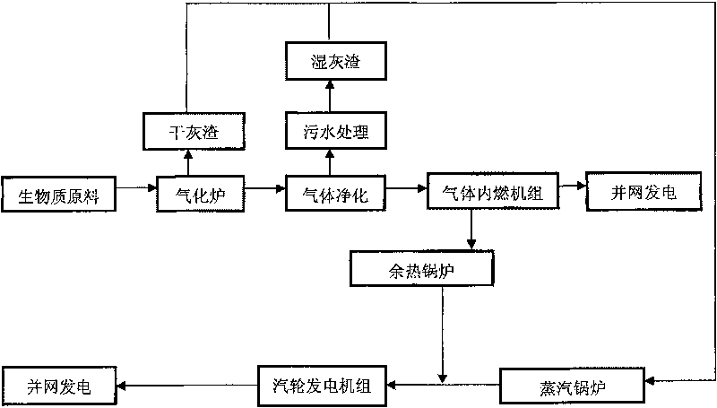
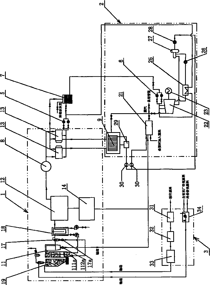
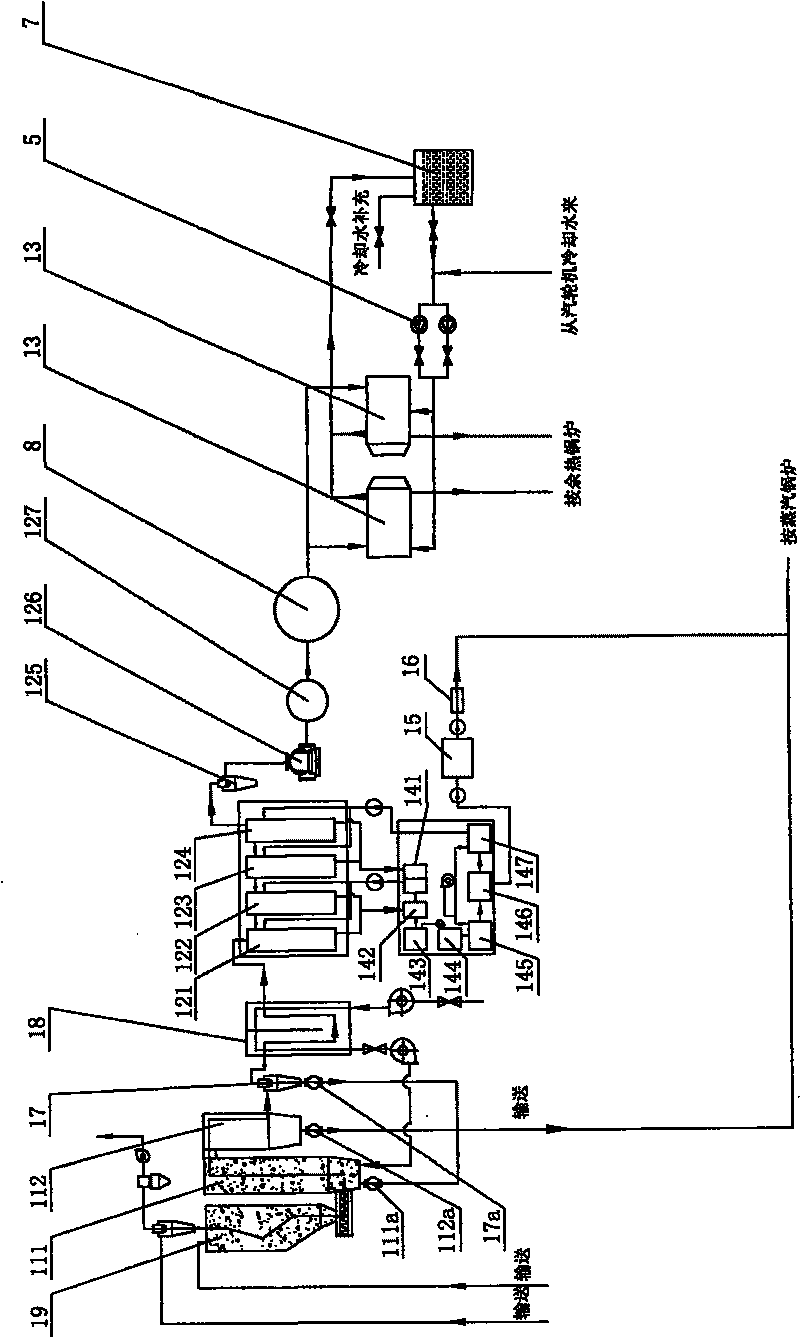
[0036] Embodiment 1 of the present invention is as Figure 1~3 As shown, the present invention can be popularized and applied by cooperating with a large rice factory to set up a power plant or setting up a biomass power plant in a grain production base. The scale of the power plant can be selected according to the local biomass resources, generally 5MW and 10MW.

[0037] The biomass power generation process of the present embodiment comprises the following steps:

[0038] (1) Treat biomass raw materials, such as crushing plant straw raw materials, and chaff raw materials can be used directly, and then gasify biomass raw materials, that is, convert solid biomass into combustible gases. The main source of these combustible gases Composition is CO, H 2 、CH 4 , CO 2 etc. The gas produced by gasification also contains certain impurities, such as ash, coke, a small amount of tar, etc.; after dedusting, decoking and purification, it is sent to the gas internal combustion unit for...

Embodiment 2

[0045] Embodiment 2 of the present invention is as Figure 4~7 As shown, the difference from the previous embodiment is that in the process of biomass power generation, in step 2, the high-temperature gas waste heat at the outlet of the gasifier 11 is first sent to the heat exchanger 18 to generate a steam-water mixture, The steam-water mixture is then fed into the waste heat boiler 9 or the steam boiler 21, or respectively sent to the waste heat boiler 9 and the steam boiler 21 for combustion to further generate superheated steam, and then transfer to step 3 to drive the turbogenerator unit to generate electricity;

[0046] In step 2, the dry ash produced after the gasification of the biomass raw material and the wet ash produced after the purification of the combustible gas are first mixed, and then sent to the steam boiler 21 for combustion;

[0047] In step 2, when necessary, the biomass raw material and ash are directly mixed in the steam boiler 21 and then burned to gene...


PUM


Abstract

The invention provides a biomass energy IGCC technology which is characterized in that the technology comprises the following steps that: (1) the biomass raw material is gasified to be converted intothe combustible gas which is dedusted and decoked as well as purified and is sent to a gas internal-combustion engine to generate electricity; (2) the biomass raw material or the clinker generated inthe gasification and power generation process in the step 1 or the mixture of the two is sent to a steam boiler to be burnt in order to generate the superheated steam; the exhaust heat of the gas internal-combustion engine of the step 1 is inlet to an exhaust-heat boiler to generate the superheated steam; (3) the superheated steam generated by the steam boiler and the exhaust-heat boiler of the step2 is sent to a turbonator set. The biomass energy IGCC technology takes full advantage of the heat energy and the product generated by each processing step in the biomass energy gasification and powe r generation process and generates electricity circularly, thereby greatly raising the power generation efficiency, taking full advantage of waste materials and lowering the running cost. The invention also discloses a power generation system for realizing the biomass energy IGCC technology.

Description

technical field [0001] The invention relates to a power generation process and a power generation system thereof, in particular to a biomass energy cycle power generation process and a power generation system thereof. Background technique [0002] New energy technology is one of the most influential technologies in the world's economic development in the 21st century. Human beings will eventually rely on the development of new energy industries to solve the global energy crisis and environmental pollution problems and achieve sustainable development. Among the renewable energy encouraged by the state, the largest one is the power generation and utilization of biomass energy. my country has abundant biomass energy resources. According to estimates, my country's theoretical biomass energy resources are about 5 billion tons. At present, the available biomass energy resources are mainly biomass waste, including crop straw, chaff, firewood, industrial organic waste and municipal ...

Claims


Application Information

Patent Timeline
Patent Type & Authority Patents(China)
IPC IPC(8): F02B43/10F02C3/28F02B63/04F01K11/02F01K17/04F22G1/12F22D11/06C10B53/02
CPCY02T10/32Y02E50/12Y02E20/14Y02E50/10Y02P20/129Y02T10/12Y02T10/30
Inventor 黄家笙林文彬
Owner 黄家笙
Why Eureka
Try Eureka